
Giant magnetoresistance array current sensor

A technology of current sensor and giant magnetoresistance, which is applied in the field of smart sensors, can solve problems such as giant magnetoresistance output unipolarity, and achieve the effect of improving real-time performance and weakening magnetic field interference

Inactive Publication Date: 2011-05-04
INST OF ELECTRICAL ENG CHINESE ACAD OF SCI
View PDF3 Cites 20 Cited by
  • Summary
  • Abstract
  • Description
  • Claims
  • Application Information

AI Technical Summary

Problems solved by technology

At present, only the AA series produced by the NVE company in the United States is relatively stable in the commercial analog giant magnetoresistance magnetic chips, but no matter whether the direction of the magnetic field is positive or negative, the output of the giant magnetoresistance is unipolar.

Method used


Image

  • Giant magnetoresistance array current sensor
  • Giant magnetoresistance array current sensor
  • Giant magnetoresistance array current sensor

Examples


Embodiment Construction

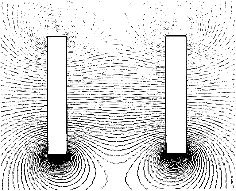
[0030] figure 1 It is a schematic structural block diagram of the present invention. Such as figure 1 As shown, the present invention includes: giant magnetoresistive chip sub-board array 1, annular PCB motherboard 2, 8-channel voltage amplifier circuit 3, 8-channel sampling and holding and A / D conversion circuit 4, and FPGA processing circuit 5. The GMR chip sub-board array 1 is composed of 8 GMR sub-boards. Each sub-board is composed of a giant magnetoresistance chip AA005-02 and two bar-shaped AlNiCo permanent magnets. The two bar-shaped permanent magnets are respectively placed at both ends of the giant magnetoresistance chip AA005-02. The direction is consistent with the magnetic sensitivity direction of giant magnetoresistive chip AA005-02. The 8 giant magnetoresistive sub-boards are evenly distributed on the ring-shaped PCB motherboard 2 with the same radius and equal angle. After the output voltage signal is amplified by the 8-channel voltage amplifier circuit 3, it...


PUM


Abstract

The invention relates to a giant magnetoresistance array current sensor comprising a giant magnetoresistance chip sub-board array (1), an annular mother PCB (printed circuit board) (2), an eight-channel amplifier circuit (3), an eight-channel sampling retaining and A / D (analog to digital) conversion circuit (4) and a FPGA (field programmable gate array) signal processing circuit (5). The giant magnetoresistance chip sub-board array (1) comprises a giant magnetoresistance chip AA005-02 and two strip-shaped aluminum-nickel-cobalt permanent magnets, wherein the aluminum-nickel-cobalt permanent magnets are arranged on two ends of the giant magnetoresistance chip AA005-02, and the magnetizing direction of the strip-shaped aluminum-nickel-cobalt permanent magnets is consistent with the magnet-sensing direction of the giant magnetoresistance chip AA005-02; eight giant magnetoresistance chip sub-boards are arranged on the annular mother PCB (2); the voltage signals outputted by the giant magnetoresistance chip AA005-02 are inputted into the eight-channel amplifier circuit (3), and then the voltage signals are amplified and made to enter the eight-channel sampling retaining and A / D conversion circuit (4); and the simulated voltage signals are converted into digital signals, and then the eight-way digital signals are processed by the FPGA signal processing circuit (5).

Description

technical field [0001] The invention relates to an intelligent sensor, in particular to a giant magnetoresistance array current measuring sensor. Background technique [0002] In order to improve energy utilization efficiency and apply renewable energy access, the current power grid is gradually developing towards a flexible smart grid characterized by intelligent control, management and analysis, which requires various sensors to monitor the current of grid lines, Real-time monitoring of parameters such as voltage, temperature and power equipment operation. [0003] Among them, the real-time accurate detection of current is one of the important tasks in the measurement of many electrical parameters. In the more than 100 years of power system development, traditional current transformers have played a pivotal role in current detection and relay protection. In connection with the construction of digital substations, traditional current transformers are increasingly exposed ...

Claims


Application Information

Patent Timeline
IPC IPC(8): G01R19/00G01R15/00
Inventor 辛守乔肖立业张国民戴少涛邱清泉刘怡许熙
Owner INST OF ELECTRICAL ENG CHINESE ACAD OF SCI
Learn More