Optical disk producing sheet
a technology of optical disks and producing sheets, applied in the direction of mechanical recording, instruments, photosensitive materials, etc., can solve the problems of increasing the production cost of optical disks, reducing the life of stampers, and contaminating stampers, so as to reduce the number of deposits formed on stampers
- Summary
- Abstract
- Description
- Claims
- Application Information
AI Technical Summary
Benefits of technology
Problems solved by technology
Method used
Image

Examples
first embodiment
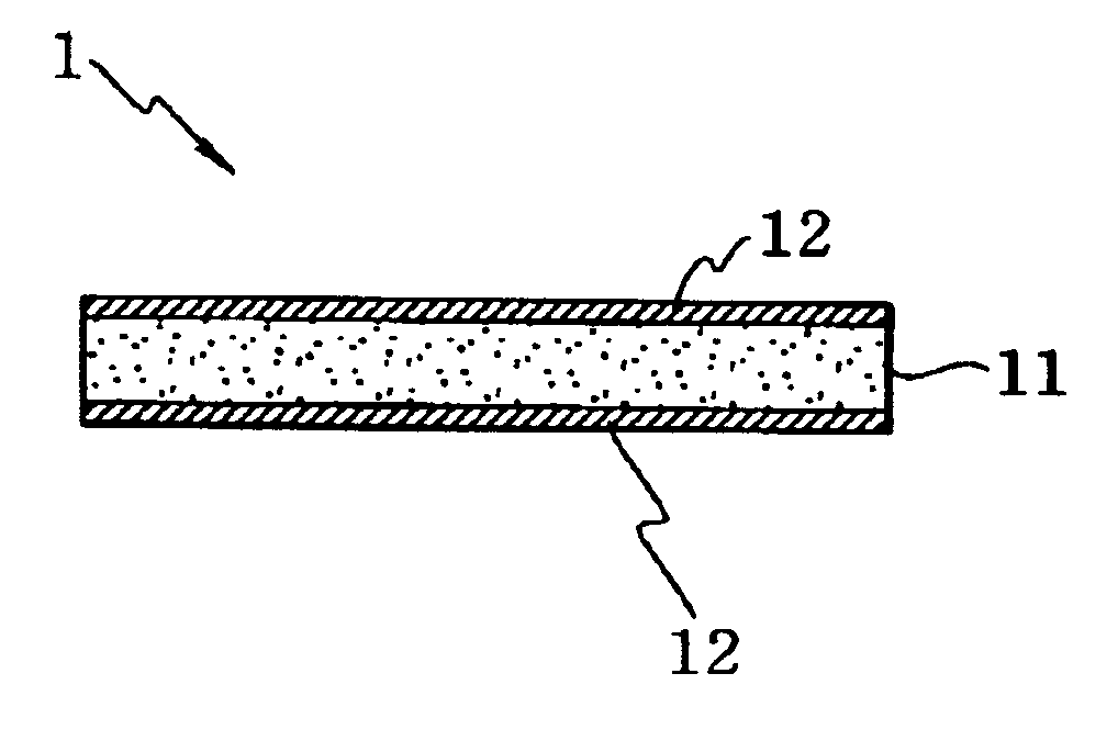
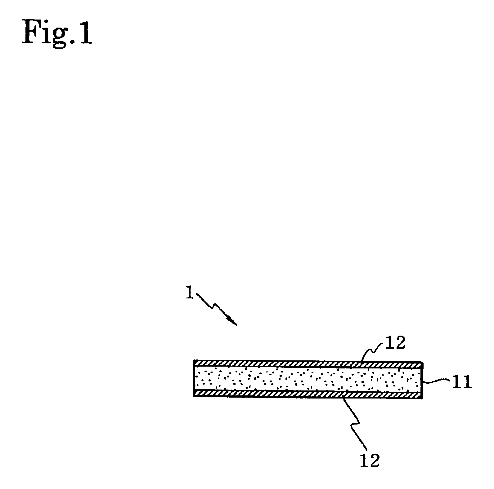
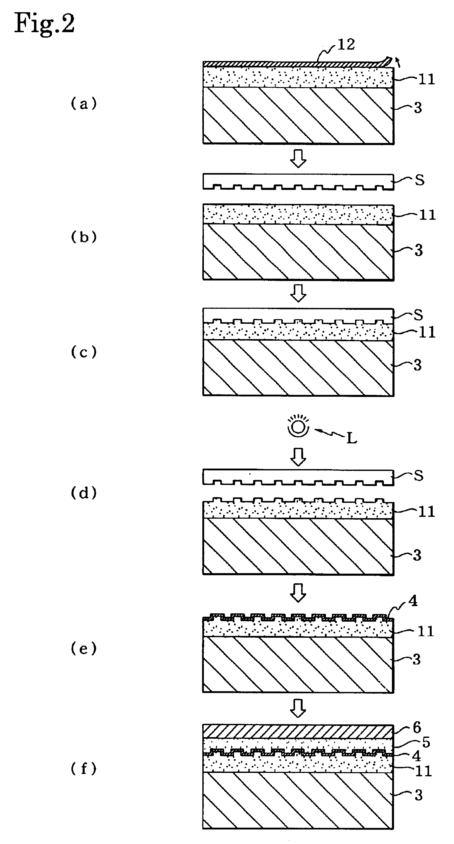
The optical disk producing sheet 1 pertaining to this embodiment comprises a stamper-receiving layer 11 and release sheets 12 laminated to both surfaces of the stamper-receiving layer 11, as shown in FIG. 1. The release sheets 12 are peeled off when the optical disk producing sheet 1 is used.
The stamper-receiving layer 11 is a layer on which concavoconvex pattern formed on the stamper is transferred and pits or grooves are formed. The stamper-receiving layer 11 comprises an energy rays-curable polymeric material. The pre-curing storage elastic modulus of the stamper-receiving layer 11 is 103 to 106 Pa, and preferably 104 to 5×10⁵ Pa.
As used herein, the measurement temperature for the “pre-curing storage elastic modulus” is the same temperature as that of the working environment in which the stamper and the optical disk producing sheet 1 are superimposed (pressed together). In other words, when the stamper and the optical disk producing sheet 1 are superimposed at room temperature, t...
second embodiment
Following is a description of an optical disk producing sheet pertaining to a second embodiment.
The optical disk producing sheet 2 pertaining to the second embodiment comprises a stamper-receiving layer 21, a protective sheet 22 laminated to one side (bottom side in FIG. 3) of the stamper-receiving layer 21, and a release sheet 23 laminated to the other side (upper side in FIG. 3) of the stamper-receiving layer 21, as shown in FIG. 3. The release sheet 23 is peeled off when the optical disk producing sheet 1 is used.
The stamper-receiving layer 21 is composed of the same material and is fashioned to the same thickness as the stamper-receiving layer 11 for the optical disk producing sheet 1 pertaining to the first embodiment described above. The release sheet 23 is composed of the same material and is fashioned to the same surface roughness (Ra) as the release sheet 12 for the optical disk producing sheet 1 pertaining to the first embodiment described above.
The protective sheet 22 of ...
example 1
Manufacture of Coating Agent A for Stamper-receiving Layer
Butyl acrylate (62 parts by weight), methyl methacrylate (10 parts by weight), and 2-hydroxyethyl acrylate (28 parts by weight) were reacted in ethyl acetate, yielding an ethyl acetate solution (solids concentration: 40 wt %) of an acrylic copolymer having hydroxyl groups for functional groups. Ethyl acetate (100 parts by weight), methacryloyl oxyethyl isocyanate (30 parts by weight, or 80.5 equivalents per 100 equivalents of the 2-hydroxyethyl acrylate in the acrylic copolymer) serving as a compound containing unsaturated groups and having isocyanate groups for substituents, and dibutyltin dilaurate (0.12 part by weight) serving as a catalyst were added to 250 parts by weight of the ethyl acetate solution of the acrylic copolymer, and a reaction was conducted for 24 hours at room temperature under a nitrogen atmosphere, yielding an energy rays-curable copolymer. The weight-average molecular weight (Mw) of the energy rays-cur...
PUM
| Property | Measurement | Unit |
|---|---|---|
| Elastic modulus | aaaaa | aaaaa |
| Elastic modulus | aaaaa | aaaaa |
| Molecular weight | aaaaa | aaaaa |
Abstract
Description
Claims
Application Information
 - R&D
- Intellectual Property
- Life Sciences
- Materials
- Tech Scout
- Unparalleled Data Quality
- Higher Quality Content
- 60% Fewer Hallucinations
Browse by: Latest US Patents, China's latest patents, Technical Efficacy Thesaurus, Application Domain, Technology Topic, Popular Technical Reports.
© 2025 PatSnap. All rights reserved.Legal|Privacy policy|Modern Slavery Act Transparency Statement|Sitemap|About US| Contact US: help@patsnap.com