
Color image formation method

a color image and formation method technology, applied in the field of color image formation method, can solve the problems of deterioration of image quality, affecting the quality of image, so as to achieve satisfactory image, reduce the effect of the change ratio of electrostatic charge amount and improve image quality

Inactive Publication Date: 2005-02-15
FUJITSU LTD +1
View PDF10 Cites 38 Cited by
  • Summary
  • Abstract
  • Description
  • Claims
  • Application Information

AI Technical Summary

Benefits of technology

It is therefore an object of the present invention to provide an image formation method that can solve the problems of the prior art technologies described above, and can form a high-quality color image by keeping the toners always at the stable degree of aggregation and with a stable charge amount.
According to the present invention, in the toner used for the color image formation apparatus, the addition amount of the external additive to the non-added toner is adjusted to 1.5 to 10.0 parts by weight based on 100 parts by weight of the non-added toner. The external additives comprise at least particles having particle diameters of 30 to 100 nm and particles having smaller particle diameters than those of the above particles. The charge amount of at least one kind of the external additives has different polarity from other charge amounts. Thus, the aggregation degree of the toner can be set to 30 to 80%, its change ratio, to 0.8 to 1.2, and the change ratio of the electrostatic charge amount on the toner can be limited to 1.0 to 1.5. Consequently, the change ratio of the aggregation degree of the toner and the change ratio of the electrostatic charge amount can be lowered even under the application condition of physical stress that occurs incessantly, and a satisfactory image can be always provided without deterioration of image quality.

Problems solved by technology

The fluidity of the toner changes during the use of the toner and invites various problems.
For example, the image density gradually lowers and the intermediate tone becomes more difficult to obtain.
Further, there is the problem resulting from the change of fluidity of the toner during the use.
That is, there is a problem of a change in the condition of the toner layer formed by a toner layer thickness-limiting blade.
Also, the pressure of the toner layer thickness-limiting blade fails to form a uniform toner layer, so that non-uniformity occurs in the toner layer thickness.
These changes of the toner with the passage of time invite image defects such as an increase in the printing density, non-uniformity of the density, a drop in reproducibility of the intermediate tone, etc, in the resulting toner image.
The problems resulting from the change of the toner with time are more critical in a color image formation apparatus because an actual color image formation apparatus operates in very many cases under a condition where toner consumption does not occur.
Under the use environment of the color image formation apparatus described above, however, degradation of the toners becomes a serious problem because replacement of the toners does not occur.
The drop in the charge amount causes problems such as photographic fog of the base and the occurrence of a negative after-image.
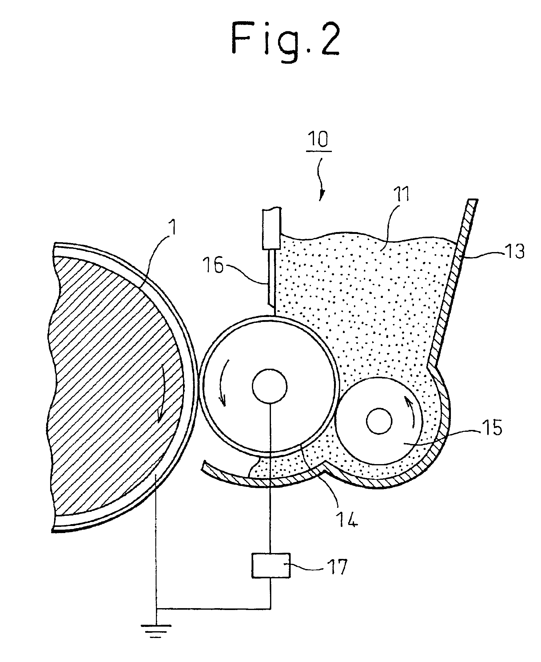
As described above, the fluctuation resulting from degradation of the toners is a serious problem for a color image formation apparatus even when it is a contact type nonmagnetic one-component developing machine.

Method used


Image

  • Color image formation method
  • Color image formation method
  • Color image formation method

Examples


example 1

Preparation of nonmagnetic toner having low toner fluidity and little fluctuation of charge amount:

(1) Preparation of toner A:binder resin: polyester resin100 parts by weight(acid value = 5, Mn = 4,500,Mw / Mn = 4.0, Tg = 60° C.)charge controller: zinc 4 parts by weightsalicylate derivativecolorant: copper phthalocyanine 4 parts by weightblue pigment (C. I. PIGMENT BLUE 15)

The mixture of the composition described above was melt-kneaded by using a roll mill and was cooled. The resulting mixture was coarsely pulverized by using a hammer mill and was further pulverized finely by using a jet mill. The resulting fine powder was classified to obtain powder having a volume mean particle diameter of 8.5 μm. This powder is referred to as “toner A”.

(2) Preparation of Toner B:

100 parts by weight of the toner A prepared as described above and 0.01 part of hydrophobic silica (mean particle diameter of primary particles=approx. 16 nm, trade name “R972D”, a product of Nippon Aerosil Co.) were mixed ...

example 2

Evaluation Test of Toners:

The change ratio of the aggregation degree and the change ratio of the electrostatic charge amount were measured for each of the toners A to H prepared as described above in the initial stage and after the continuous operation. At the same time, the quality of the printed images was compared and examined. To conduct this evaluation test, each toner inside the toner container that did not receive the stress was collected as the initial toner. Each toner on the back of the developing roller, where the toner was believed to be most likely to receive the stress inside the toner container, was collected as the toner after the continuous operation.

[Measurement of Aggregation Degree]

The aggregation degree of each toner was measured in the following way by using a powder tester “PT-D” (a product of Hosokawa Micron K. K.).

(1) Each toner as the measurement object was left to stand for 12 hours in a measurement environment.

(2) A sieve of a three-layered structure havi...


PUM


Abstract

In a method for forming a multicolored toner image in accordance with an electrophotographic process, the addition amount of external additives to a non-added toner is 1.5 to 10.0 parts by weight per 100 parts by weight of the non-added toner in each developing step, the aggregation degree of the toner is within the range of 30 to 80%, and the change ratio of the aggregation degree satisfies the relation:0.8≦(initial aggregation degree / aggregation degree after no-load revolution of developing portion for 20 hours)≦1.2. According to this method, it becomes possible to form a high-quality color image while a toner always keeps a stable degree of aggregation and a charge amount.

Description

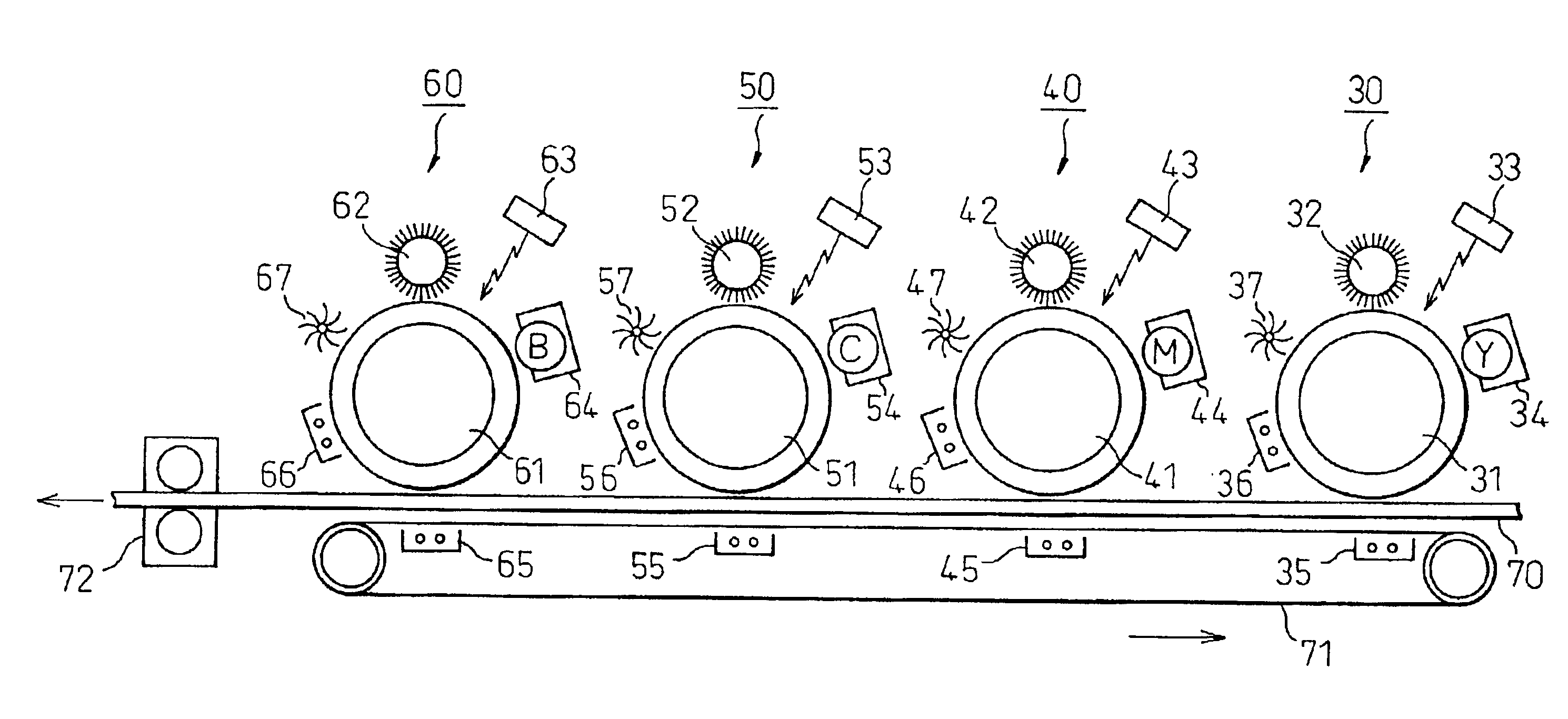
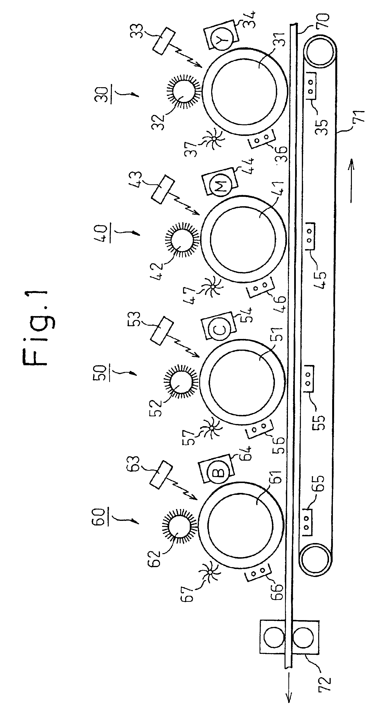
BACKGROUND OF THE INVENTION1. Field of the InventionThe present invention relates to an image formation method. More particularly, the present invention relates to a method for forming a color image in an electrographic devices such as an electrophotographic copying machine, an electrophotographic printer, and so forth. Among others, the present invention relates particularly to a color image formation method that will be useful for a color image formation system that disposes a plurality of image formation units each for forming a monochromatic image, particularly those image formation units which use a contact type nonmagnetic one-component developing method, in a conveying direction of sheets, and superposes these monochromatic images with one another to form a color image.2. Description of the Related ArtVarious image formation methods are available for forming a color image on an image recording medium such as a sheet of paper, as is well known in the art. An image formation ap...

Claims


Application Information

Patent Timeline
IPC IPC(8): G03G15/01G03G9/08G03G9/09
CPCG03G15/0126G03G2215/0119
Inventor YAMAMOTO, TAKASHINAKAMURA, MASAEKINOSHITA, MASAKAZUKATAGIRI, YOSHIMICHIKURAMOTO, SHIN-ICHITOSAKA, HACHIROYAMASHITA, HIROSHIUCHINOKURA, OSAMU
Owner FUJITSU LTD
Learn More