
Cutting tooth for trencher chain

a cutting tooth and chain technology, applied in cutting machines, cutting machines, cutting machines, etc., can solve the problems of reducing the effectiveness of cutters, affecting the production efficiency of trenching, and affecting the efficiency of cutters, so as to improve the excavation efficiency, reduce power requirements, and improve the effect of spoilag

Inactive Publication Date: 2005-02-15
HUNTER WILLIAM D +1
View PDF12 Cites 58 Cited by
  • Summary
  • Abstract
  • Description
  • Claims
  • Application Information

AI Technical Summary

Benefits of technology

The cutter described therein is manufactured from a special alloy that is then heat treated and tempered to achieve high strength and hardness. The entire cutter tooth is of the same consistent temper and tensile strength, not just certain areas. This material and the heat treatment render a cutter that is stronger, harder, and more durable than carbon steel formed plate cutters.
This homogeneous structure can be resharpened when it starts wearing from use, thereby extending the useful life. The sharpening method can be achieved with the teeth installed on the trencher chain by passing a hand held grinder over the forward angular cutting face or by removing and grinding and then reinstalling. The regrinding process removes the dulled surface and relieves the material back to reform a new cutting plane beneath the previous one.
The principal object of the present invention is to provide a tooth with more efficient trenching production, with less power requirements from the drive system, and better spoils excavation.
Another object of the invention is the provide a more versatile tooth that cuts both soft soils and rocky soils while providing excellent spoils excavation with minimum back fall in the trench.
Another object of the invention is to provide a longer life tooth of extreme hardness that can be resharpened.

Problems solved by technology

Cup tooth cutters are effective when used in soft soils, but because of the relative lack of rigidity and temper, they abrade and erode quickly when used on hard mineral soils.
When cuttings pack into the cutter in this manner, the cutter cannot carry additional materials and the effectiveness of the cutters is greatly diminished.
The effectiveness of this design is questioned.
These cutters are also ineffective as hard mineral fracturing teeth due to the blunt and relatively thin forward edges that contact the soil.

Method used


Image

  • Cutting tooth for trencher chain
  • Cutting tooth for trencher chain
  • Cutting tooth for trencher chain

Examples


Embodiment Construction

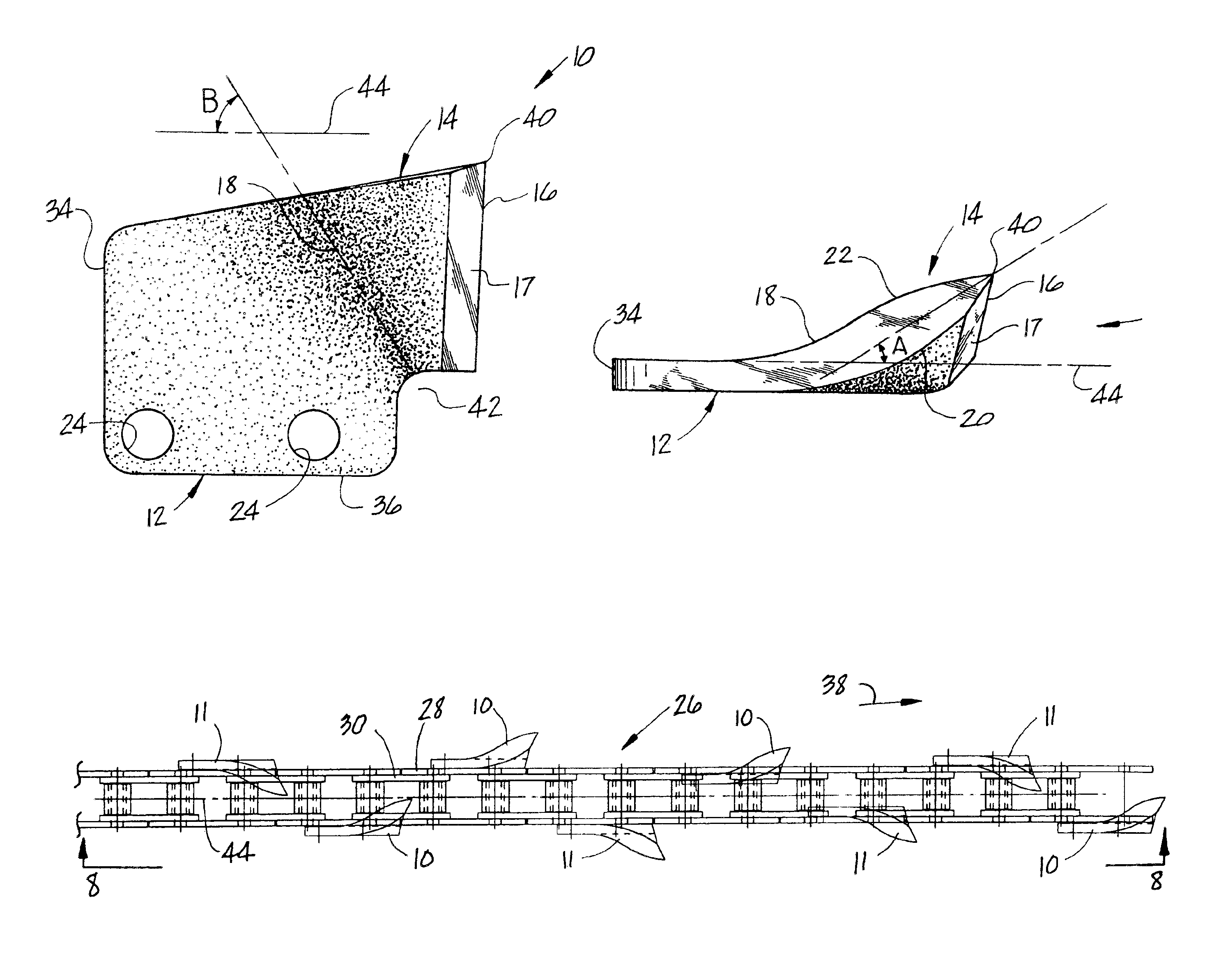
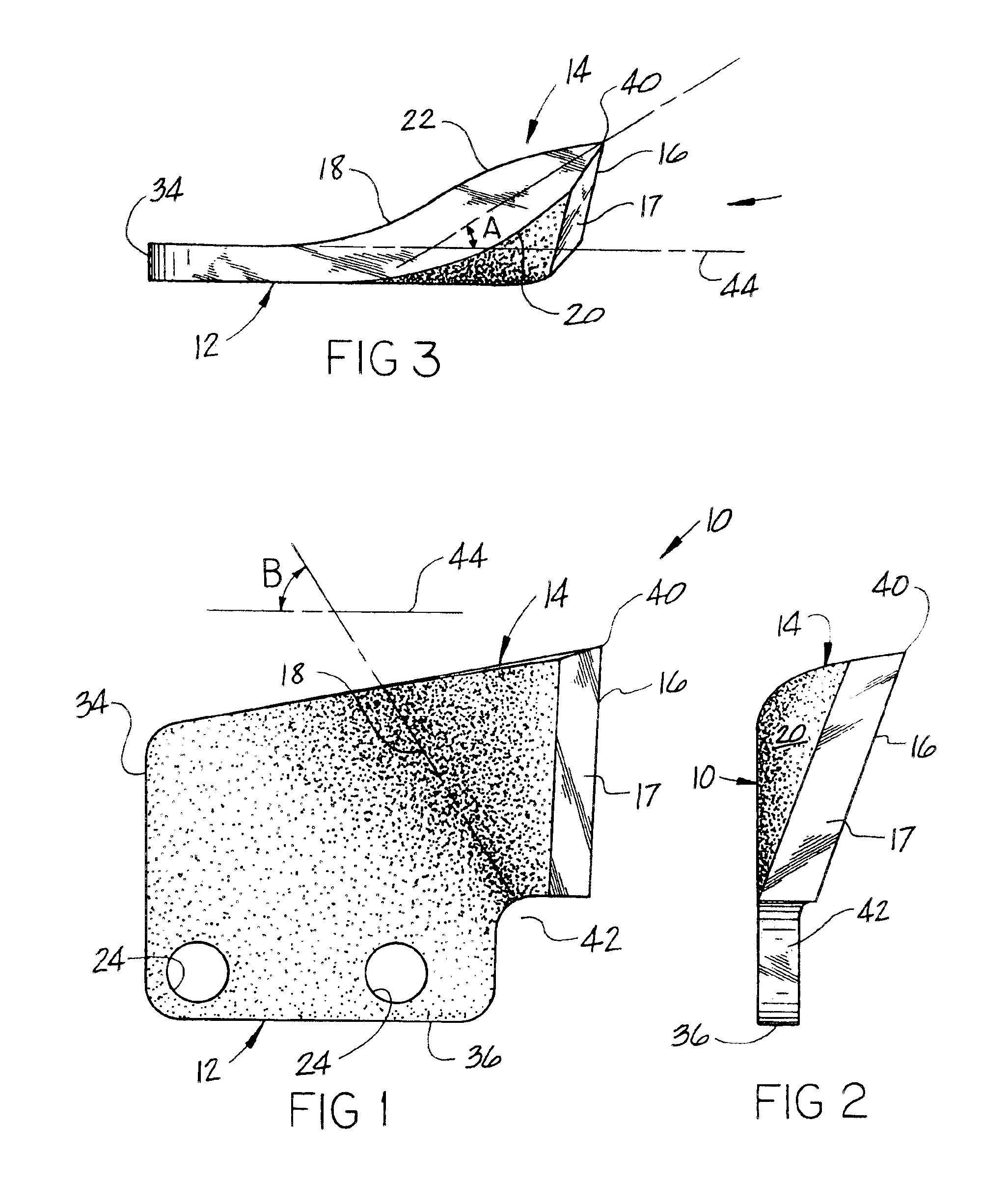
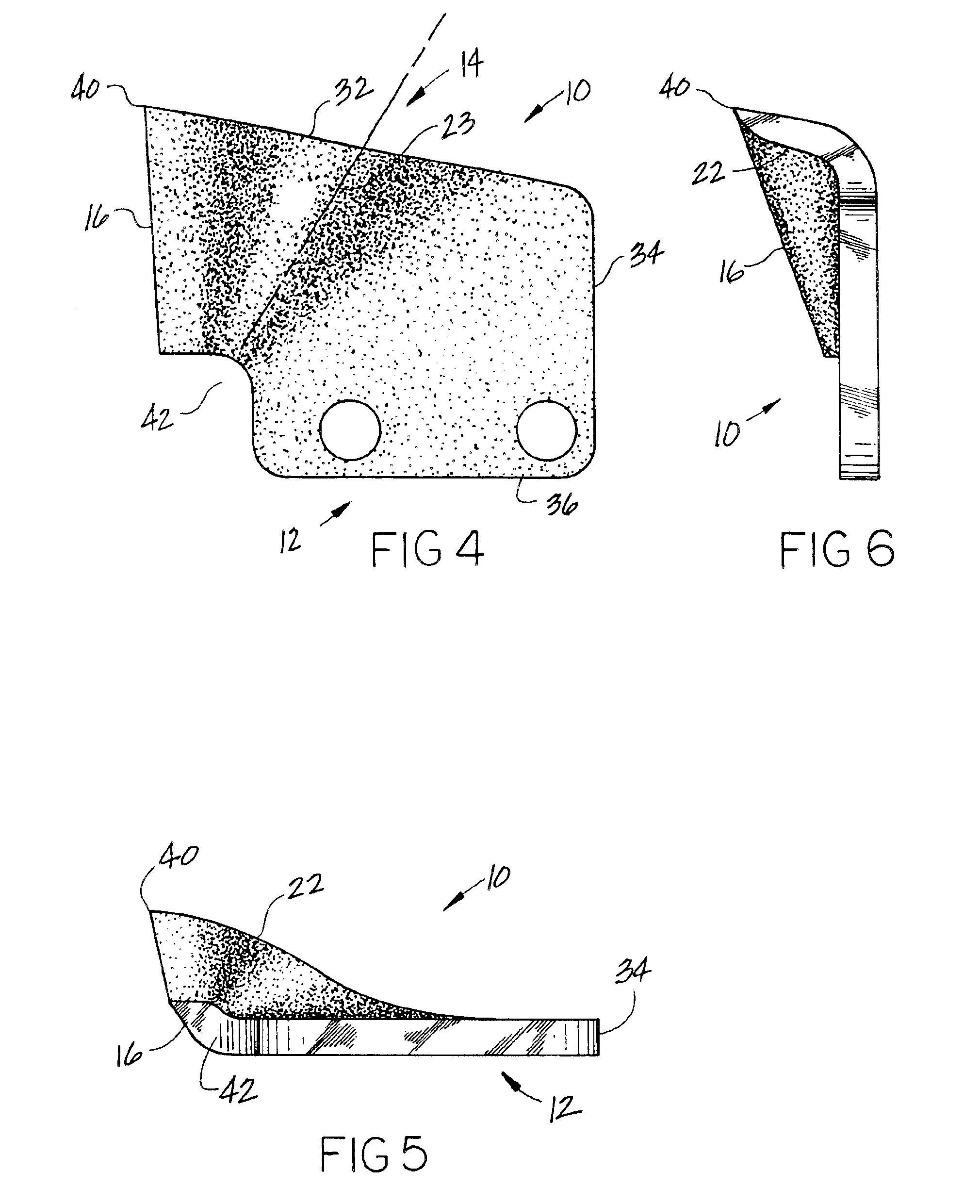
FIGS. 7 and 8 show top and side views of a conventional trencher chain generally identified by reference numeral 26 which supports a plurality of the trencher teeth of the present invention which are identified by reference numerals 10 and 11, one being the mirror image of the other. Trencher chains are typically used by trenchers in the prior art, such as illustrated and described in U.S. Pat. No. 6,154,987. The chain is supported by two sprockets located at opposite ends of a boom, which drive the chain in the direction indicated by arrow 38. In it's digging function the chain 26 operates upside down from its FIG. 8 position with the chain exiting the ground at an acute angle to the surface, which then rides around a sprocket and reverses its direction traveling back into the previously cut trench.

Chain 26 includes mounting links 28 connected by smaller bridging links 30 with bolts that connect the links but are not shown. Mounting links 28 include a pair of mounting holes 25 wher...


PUM


Abstract

A cutting tooth used on an endless chain-trenching machine to fracture and excavate the ground. The tooth includes a mounting portion for attachment to the chain and a cutting portion having a straight cutting edge at the leading end of the tooth positioned normal to the direction movement of the chain. The cutting portion is aligned from the mounting at an acute angle to the plane of the mounting portion and including convex surfaces on both sides of the cutting portion and a juncture line between the mounting portion and the cutting portion forms an acute angle with the direction movement of the chain whereby the cuttings produced by the tooth are lifted away by the chain as the chain is digging.

Description

FIELD OF THE INVENTIONThis invention relates to a cutting tooth used on endless chain trenching machines. Teeth are affixed to the chain and driven into the soil to fracture and excavate the materials thereby forming a trench or ditch in which are laid underground pipe and cables.BACKGROUND OF THE INVENTIONIt is well established by practice within the trenching service industry that it is desirable for the trench-cutting device to fracture the soil and excavate the spoils efficiently. Most trenchers include a tractor unit equipped with an elongated boom, which supports an endless chain power driven over sprockets at opposing ends of the boom. Cutting teeth are removably affixed to the chain.There have been many attempts to develop teeth that accomplish both functions, but they have either been more efficient at fracturing or excavating. The variety of soil conditions affects the performance of each type of tooth.Some of the early tooth designs were derived from mining breaker teeth....

Claims


Application Information

Patent Timeline
Patent Type & Authority Patents(United States)
IPC IPC(8): E02F9/28
CPCE02F9/2808
Inventor HUNTER, WILLIAM D.BECKER, RONALD C.
Owner HUNTER WILLIAM D
Learn More