
Measurement of fluorescence using capillary isoelectric focusing

a fluorescence and isoelectric focusing technology, applied in the direction of semi-permeable membranes, material analysis by electric/magnetic means, electrolysis components, etc., can solve the problems of difficult to obtain reproducible qualitative and quantitative, high dynamic noise, and inability to use more conventional separatory methods

Inactive Publication Date: 2005-02-08
PAWLISZYN JANUSZ
View PDF1 Cites 43 Cited by
  • Summary
  • Abstract
  • Description
  • Claims
  • Application Information

AI Technical Summary

Problems solved by technology

This is generally not possible with more conventional separatory methods, even high performance liquid chromatography (HPLC).
This mobilization step in CIEF requires extra time and distorts the focused zone, thus making it difficult to obtain reproducible qualitative and quantitative results.
Because the capillary in the system also functions as a lens, any small change in the position of the capillary results in a large shift in the light path through the cylindrical capillary, causing high dynamic noise.
However, the application of LIF to CIEF presents difficult problems of alignment of the source of excitation light with the small internal diameter capillary and the collection of emission fluorescence.
In particular, the radiation of the sample-containing capillary in a direction perpendicular to the capillary axis gives only a very short excitation path and gives rise to the difficulty of interference by light scattered from the wall of the capillary.
Moreover, their method is not adaptable for whole column imaging detection.

Method used


Image

  • Measurement of fluorescence using capillary isoelectric focusing
  • Measurement of fluorescence using capillary isoelectric focusing
  • Measurement of fluorescence using capillary isoelectric focusing

Examples


Embodiment Construction

Apparatus

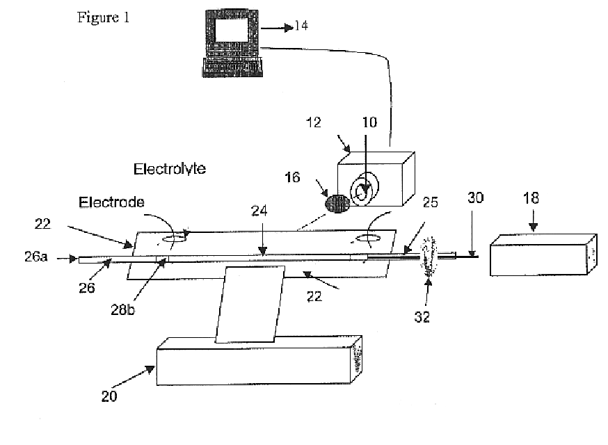
A schematic of the axially illuminated LIF WCID is shown in FIG. 1. In the system, a small UV lens 10 (A4869, Hamamatsu Inc, Japan) was coupled to an UV-sensitive CCD camera 12, which was controlled by a ST-130 controller (TEA / CCD-1752 / PF / UV, 14, Princeton Instrument, Trenton, N.J. USA). An edge filter 16 (LL-550-s-577 D, Corion, Mass., USA) was placed in front of the camera. The camera 12 was thermoelectrically cooled down to −40° C. and all the parameters were adjusted to get a clear image. The electropherogram was obtained by binning perpendicular to the capillary axis to get a better signal to noise ratio.

The power supply (not illustrated) was a RE-3002B (Regulated High-voltage supply, Mass). An air-cooled argon ion laser 18 (Cyonics, CA) was used as the excitation source. An x-y translatable stage 20 was used to facilitate adjusting the capillary cartridge to let the laser light pass axially through the capillary.

A cartridge 22 carrying separation capillary 24 is also ...


PUM

PropertyMeasurementUnit
pore sizeaaaaaaaaaa
pore sizeaaaaaaaaaa
pore sizeaaaaaaaaaa

Abstract

Improved apparatus is disclosed for carrying out axially illuminated laser induced fluorescence whole-column imaging detection in the capillary isoelectric focusing of proteins. The separation capillary was made of low refractive index Teflon conditioned with methylcellulose to reduce electroosmotic flow and a small amount of high refractive index organic solvent (glycerol) was added to the sample mixture. It was found that an axially directed laser excitation beam was propagated essentially with total internal reflection, so that minimum interference arose from stray light or from scattering light originating from the wall of the capillary. With the naturally fluorescent protein R-phycoerythrin, a concentration detection limit LOD 10−11 M or mass LOD 10−17 Mo was obtained.

Description

BACKGROUND OF THE INVENTIONThis invention relates to the detection of analytes separated from a mixture by capillary isoelectric focusing (CIEF) using axially illuminated laser induced fluorescence (LIF) and whole-column imaging detection (WCID) of fluorescence emitted by the analytes.BRIEF REVIEW OF THE PRIOR ARTThe publications referred to in what follows and identified by footnotes are incorporated by reference herein for their teachings as to capillary electrophoretic techniques.Capillary electrophoresis (CE) has been established as an important separation method in bioanalytical chemistry. Separation and detection of very small amounts of biological samples, about pL-nL volumes, can be achieved with CE. This is generally not possible with more conventional separatory methods, even high performance liquid chromatography (HPLC). There are several CE separation methods in use for different kinds of samples. They include capillary zone electrophoresis, moving boundary capillary ele...

Claims


Application Information

Patent Timeline
Patent Type & Authority Patents(United States)
IPC IPC(8): G01N27/447G01N21/64
CPCG01N27/44795G01N27/44721
Inventor PAWLISZYN, JANUSZWU, XING-ZHENGHUANG, TIEMIN
Owner PAWLISZYN JANUSZ
Learn More