
GPS device for measuring wave height and current direction and speed and GPS system for measuring wave height and current direction and speed

a technology of wave height and current direction, applied in the direction of instruments, open water survey, transmission, etc., can solve the problems of degrading the accuracy of wave height measurements, limiting the measurable distance from the sea bottom to the sea surface, and limited usability range of the devices, so as to improve the accuracy in the height direction, high accuracy, and high accuracy

Inactive Publication Date: 2005-01-25
JAPAN AEROSPACE EXPLORATION AGENCY
View PDF9 Cites 19 Cited by
  • Summary
  • Abstract
  • Description
  • Claims
  • Application Information

AI Technical Summary

Benefits of technology

It is an object of the present invention to overcome the above-described drawbacks and to provide at a low cost a device for measuring the wave height and current direction and speed, which is capable of accurately measuring the wave height and current direction and speed in any position on the sea or ocean and also a system for measuring the wave height and current direction and speed which uses such a device.
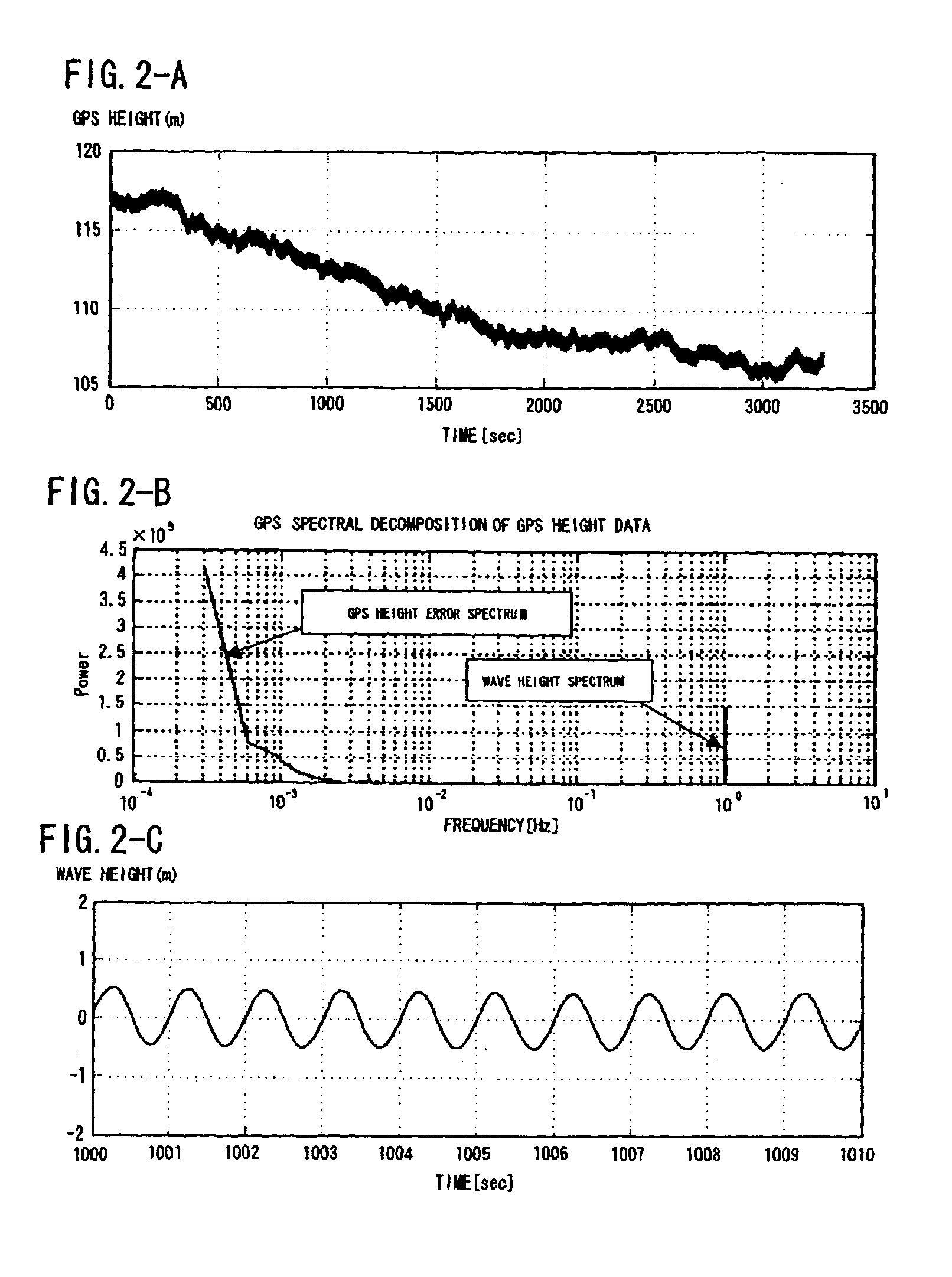
In any of the above-described GPS systems for measuring the wave height and current direction and speed, the data processing unit can have installed therein a processing software for conducting the high-pass filter processing and smoothing processing of the position data for calculating the wave height and current direction and speed. Conducting the high-pass filter processing and smoothing processing of the position data with the processing software makes it possible to remove the GPS ephemeris error, atmosphere delay error, multipath error, and the like, contained in the height data for the floating body measured with the GPS receiver and to increase the accuracy in the height direction obtained by the independent GPS navigation method. In this case, appropriately determining the cut-off frequency of the high-pass filter enables the wave height to be measured with a high accuracy based on the swinging spectrum of the waves in the vertical direction, and appropriately determining the smoothing time (or a cut-off frequency of a low-pass filter) in smoothing processing (or low-pass filter processing) of the data relating to position in a horizontal plane enables the current direction and speed to be measured with a high accuracy based on the current information in a horizontal plane of the waves.

Problems solved by technology

However, a variety of problems were encountered when the devices for measuring the wave height of those four types were used for accurate measurement of wave height in a random point on the sea or ocean.
Thus, with the ultrasonic and hydraulic devices for measuring the wave height, limitation is placed on the measurable distance from the sea bottom to the sea surface.
Therefore, the wave height could be measured only in the sea with a depth of several dozen meters and the usability range of the devices was limited.
However, the problem inherent to devices of this type was that the detected vertical acceleration data contained errors and those errors were accumulated by two-time integration, thereby degrading the accuracy of wave height measurements.
Further, the common problem of the devices of those four types was that the cost of the entire device was high because it used expensive measurement sensors.
Such devices measure the tidal current as changes in the electric field, but because they are installed in an immersed state on the sea bottom, the current direction and speed in the vicinity of sea surface cannot be measured.
Furthermore, because measurements are conducted in a single point, the tidal current in a wide range cannot be measured.
One more problem is that the entire device is very expensive because costly sensors are employed.
However, with the kinematic positioning method, a GPS station serving as a reference point disposed on the ground is required and the base line length to the measurement point is limited to no more than 10 km.
Therefore, from the standpoint of practical use and cost, the problem is that the system is difficult to construct and use.
As described hereinabove, a variety of drawbacks are inherent to the devices for measuring the wave height and current direction and speed that have already found practical use.
Accordingly, the problem that should be solved is in measuring directly the wave height and the flow of fluid in the vicinity of the water surface, which changes the position of a floating body, at any point on the sea, a lake or a marsh by conducting accurate measurements of the three-dimensional position of the floating body that flows on the sea, lake, or marsh.

Method used


Image

  • GPS device for measuring wave height and current direction and speed and GPS system for measuring wave height and current direction and speed
  • GPS device for measuring wave height and current direction and speed and GPS system for measuring wave height and current direction and speed
  • GPS device for measuring wave height and current direction and speed and GPS system for measuring wave height and current direction and speed

Examples


Embodiment Construction

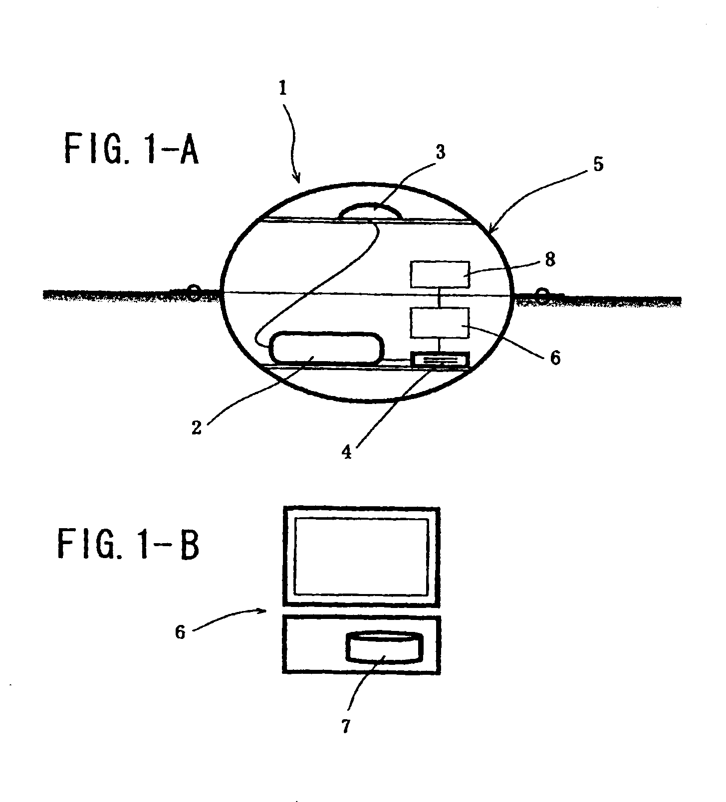
The GPS device for measuring the wave height and current direction and speed and GPS system for measuring the wave height and current direction and speed in accordance with the present invention will be described below with reference to the appended drawings. FIG. 1 is a schematic view illustrating an embodiment of the GPS device for measuring the wave height and current direction and speed in accordance with the present invention, wherein the inside of the GPS device for measuring the wave height and current direction and speed is shown in the cross section thereof.

With the GPS device 1 for measuring the wave height and current direction and speed (for the sake of simplicity it will be hereinbelow referred to as “measurement device 1”) as shown in FIG. 1-A and a measurement system using the measurement device 1, the measurement device 1 floats on the surface of ocean, sea, lake, marsh, river, and the like, without being anchored to the sea bottom or the like. Therefore, the device ...


PUM


Abstract

The present invention provides a GPS device for measuring the wave height and current direction and speed, which is capable of accurately measuring the wave height (height of the waves) and current direction and speed (tidal current) in any point on the sea, ocean, lake, or marsh, and to a system using such a device. The GPS receiver 2 of the GPS device 1 for measuring the wave height and current direction and speed processes the GPS signals received with the GPS antenna 3 and measures the three-dimensional position of antenna 3. The three-dimensional position data are recorded by the data recording unit 4 connected to the GPS receiver 2. When the floating body 5 having those devices 2-4 installed thereon floats on the sea or ocean, it moves together with the waves and tidal current in the present location. The software 7 for conducting high-pass filter processing and smoothing processing is installed in the data processing unit 6, and the data on the wave height and current direction and speed are output, while the errors are being removed from the three-dimensional position data recorded in the data recording unit 4.

Description

BACKGROUND OF THE INVENTION1. Field of the InventionThe present invention relates to a GPS device for measuring the wave height and current direction and speed, which can be used as an observation device such as an oceanological observation device by measuring the height of the waves and the frequency spectrum thereof, and to a GPS system for measuring the wave height and current direction and speed using such a device.2. Description of the Related ArtMarine research, which is essential for the survival of people, has been conducted with the object of collecting fundamental data for designing vessels, predicting weather changes by measuring tidal currents, and preventing disasters at sea. Devices for measuring the wave height and current direction and speed have been suggested as oceanological observation devices suitable for such marine research. Devices of four types for measuring the wave height, that is, ultrasonic, hydraulic, step-type, and accelerometric devices, have already ...

Claims


Application Information

Patent Timeline
IPC IPC(8): G01C13/00G01S1/00G01S19/14G01S19/19
CPCG01C13/002G01S19/39G01S19/35G01S19/14G01S19/396
Inventor HARIGAE, MASATOSHIYAMAGUCHI, ISAOKASAI, TOKIO
Owner JAPAN AEROSPACE EXPLORATION AGENCY
Learn More