
Imprint lithography template comprising alignment marks

a technology of alignment marks and printing lithography, which is applied in the direction of printing, instruments, photomechanical equipment, etc., can solve the problems of more difficult to produce sub-100 nm structures, and achieve the effects of avoiding stiction, high viscosity friction, and avoiding stiction

Inactive Publication Date: 2005-01-11
BOARD OF RGT THE UNIV OF TEXAS SYST
View PDF97 Cites 131 Cited by
  • Summary
  • Abstract
  • Description
  • Claims
  • Application Information

AI Technical Summary

Benefits of technology

Using a separate alignment for each semiconductor device produced on a substrate may be a time intensive process. To minimize processing delays, global alignment processing may be used. Global alignment processing uses an initial alignment evaluation to allow processing of additional devices without further alignment. In one embodiment, an alignment of the template with the substrate may be performed at a first portion of the substrate. After the template is aligned with the substrate a patterned layer may be formed using the above-described imprint lithography process. The positioning of the template with respect to the substrate in order to achieve the correct alignment may be herein referred to as the “calibration orientation.” The calibration orientation may be determined by looking at a single portion of the substrate or at multiple portions of the substrate. The calibration orientation may be determined and recorded. After processing, the template may be moved (commonly referred to as “stepped”) to the next portion of the substrate to be processed. The movement of the substrate with respect to the template may be very precisely controlled such that the change in position of the substrate with respect to the template may be accurately determined. After movement of the substrate, the orientation of the template with respect to the substrate may be determined and compared the calibration orientation. The template position may be altered to match the calibration orientation without having to check the alignment of the template with alignment marks. This may improve processing speed and overall throughput when using imprint lithography processing.
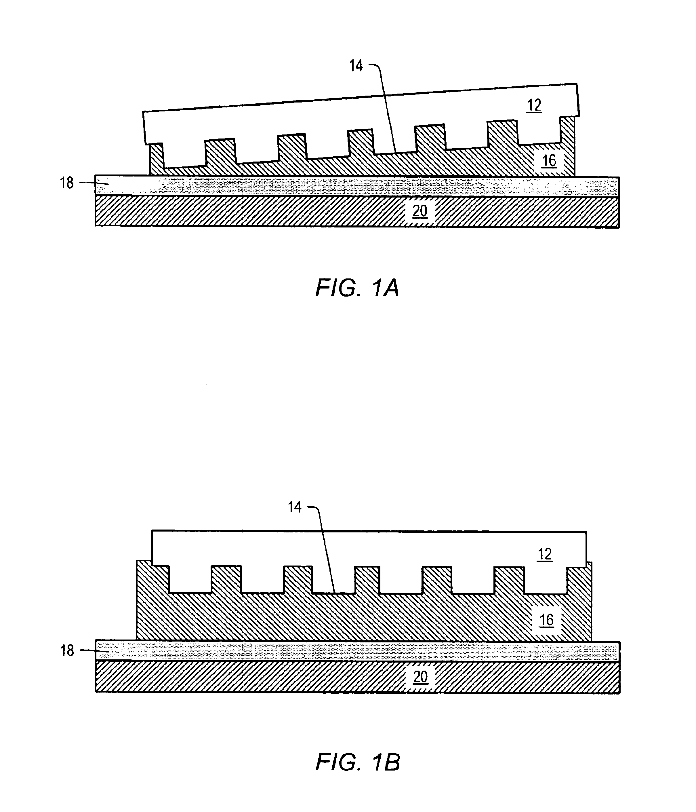
An advantage of the above-described embodiments is that by measuring and correcting overlay errors while the template and substrate is maintained at an optimal gap, the error correction can be achieved by avoiding stiction and high viscous friction. This optimal gap is high enough to avoid stiction and high viscous friction, while it is low enough that the induced overlay error during the closing-gap motion between the template and substrate can be also minimized.

Problems solved by technology

In imprint lithography, the use of high viscosity liquids may make it more difficult to produce sub 100 nm structures.

Method used


Image

  • Imprint lithography template comprising alignment marks
  • Imprint lithography template comprising alignment marks
  • Imprint lithography template comprising alignment marks

Examples


second embodiment

an X-Y translation stage is depicted in FIG. 17, and generally referenced by numeral 1700. To provide a similar range of motion to that of X-Y stage 1600, stage 1700 may have a foot print of about 29 inches by 29 inches and a height of about 15 inches (including a wafer chuck). Stages 1600 and 1700 differ mainly in that additional linkages 1701 are oriented vertically, thereby providing additional load bearing support for the translation stage.

Both X-Y stage 1600 and X-Y stage 1700 are flexure based systems. Flexures are widely used in precision machines since they may offer frictionless, particle-free and low maintenance operation. Flexures may also provide extremely high resolution. However, most flexure based systems may possess limited ranges of motion (e.g., sub mm range of motion). Embodiments disclosed herein may have a range of motion of more than 12 inches. It is believed that such stages may be cost-effective for lithographic applications, particularly in vacuum. Further, ...


PUM

PropertyMeasurementUnit
sizeaaaaaaaaaa
wavelengthaaaaaaaaaa
viscosityaaaaaaaaaa

Abstract

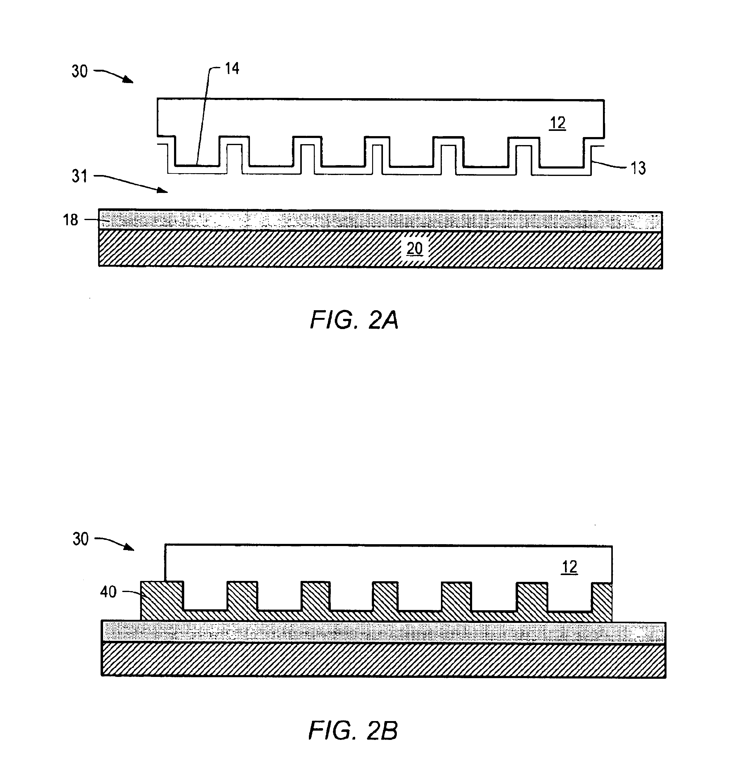
A system of determining and correcting alignment during imprint lithography process is described. During an imprint lithographic process the template may be aligned with the substrate by the use of alignment marks disposed on both the template and substrate. The alignment may be determined and corrected for before the layer is processed.

Description

BACKGROUND OF THE INVENTIONThe present invention relates to methods and, systems to achieve high-resolution overlay alignment for imprint lithography processes.Imprint lithography is a technique that is capable of printing features that are smaller than 50 nm in size on a substrate. Imprint lithography may have the potential to replace photolithography as the choice for semiconductor manufacturing in the sub-100 nm regime. Several imprint lithography processes have been introduced during 1990s. However, most of them have limitations that preclude them from use as a practical substitute for photolithography. The limitations of these prior techniques include, for example, high temperature variations, the need for high pressures and the usage of flexible templates.Recently, imprint lithography processes may be used to transfer high resolution patterns from a quartz template onto substrate surfaces at room temperature and with the use of low pressures. In the Step and Flash Imprint Lith...

Claims


Application Information

Patent Timeline
Patent Type & Authority Patents(United States)
IPC IPC(8): B29C35/08B29C37/00G03F7/00G02B5/18G03F7/20H01L21/027
CPCB29C35/0888B29C37/0053B29C43/003B29C43/021B82Y10/00B82Y40/00G03F7/0002G03F9/00B29C2035/0827Y10T428/24802Y10S101/36B29C2043/025B29C37/005
Inventor SREENIVASAN, SIDLGATA V.CHOI, BYUNG J.COLBURN, MATTHEWBAILEY, TODD
Owner BOARD OF RGT THE UNIV OF TEXAS SYST
Learn More