
Photoionization detector with multiple ionization cells

a technology of ionization cell and detector, applied in the field of photoionization detector, can solve the problems of generating less accurate results, uneven spacing of electrodes, and negative impact on the overall sensitivity of the detector

Inactive Publication Date: 2005-01-11
KOLAJA ROBERT J +2
View PDF13 Cites 8 Cited by
  • Summary
  • Abstract
  • Description
  • Claims
  • Application Information

AI Technical Summary

Benefits of technology

An ultraviolet radiation source is used as the source of high energy photons and the UV radiation is arranged to pass into a series of ionization cells, in which any ionizable compounds are ionized. The sequence of ionization cells can be continued so long as the intensity of the UV radiation remains sufficient to produce a measurable number of ions. The ionization cells each have at least one inlet and at least one outlet through which fluids may enter and exit the cells. The fluids in the respective ionization cells are substantially prevented from contacting each other and potentially contaminating each other and the cells are substantially sealed from the ambient environment.

Problems solved by technology

Improperly spaced electrodes, either too closely spaced or too widely spaced, will have a negative impact on the overall sensitivity of the detector.
Unduly large internal volumes allow the sample to diffuse and generate results that are less accurate.
Volumes that are poorly swept, such as holes or tubes that have no exit, or unnecessary changes in cross-sectional areas of the flowpath also allow the sample to diffuse and can allow the sample to reside in the poorly swept volume even after an analysis is complete, and such residual sample can then contaminate a subsequent analysis.
A PID alone typically cannot provide a user with information to distinguish the specific molecules and concentrations of a number of types of molecules that are in a sample.
However, if there is more than one type of molecule that is thus ionized, the user will be unable to discern the molecules that are present, the concentrations that are present, nor the number of different types of molecules present.
Though it is advantageous to use a chromatographic column to introduce a fluid to the PID, there is a significant delay between the time a fluid sample is collected and the time the various chemical compounds are eluted from the chromatographic column to be measured by the PID.
Though it is advantageous for a chemical compound detection instrument to allow for both types of operation, existing PIDs cannot reconcile the conflicting requirements of the variety of applications.

Method used


Image

  • Photoionization detector with multiple ionization cells
  • Photoionization detector with multiple ionization cells
  • Photoionization detector with multiple ionization cells

Examples


Embodiment Construction

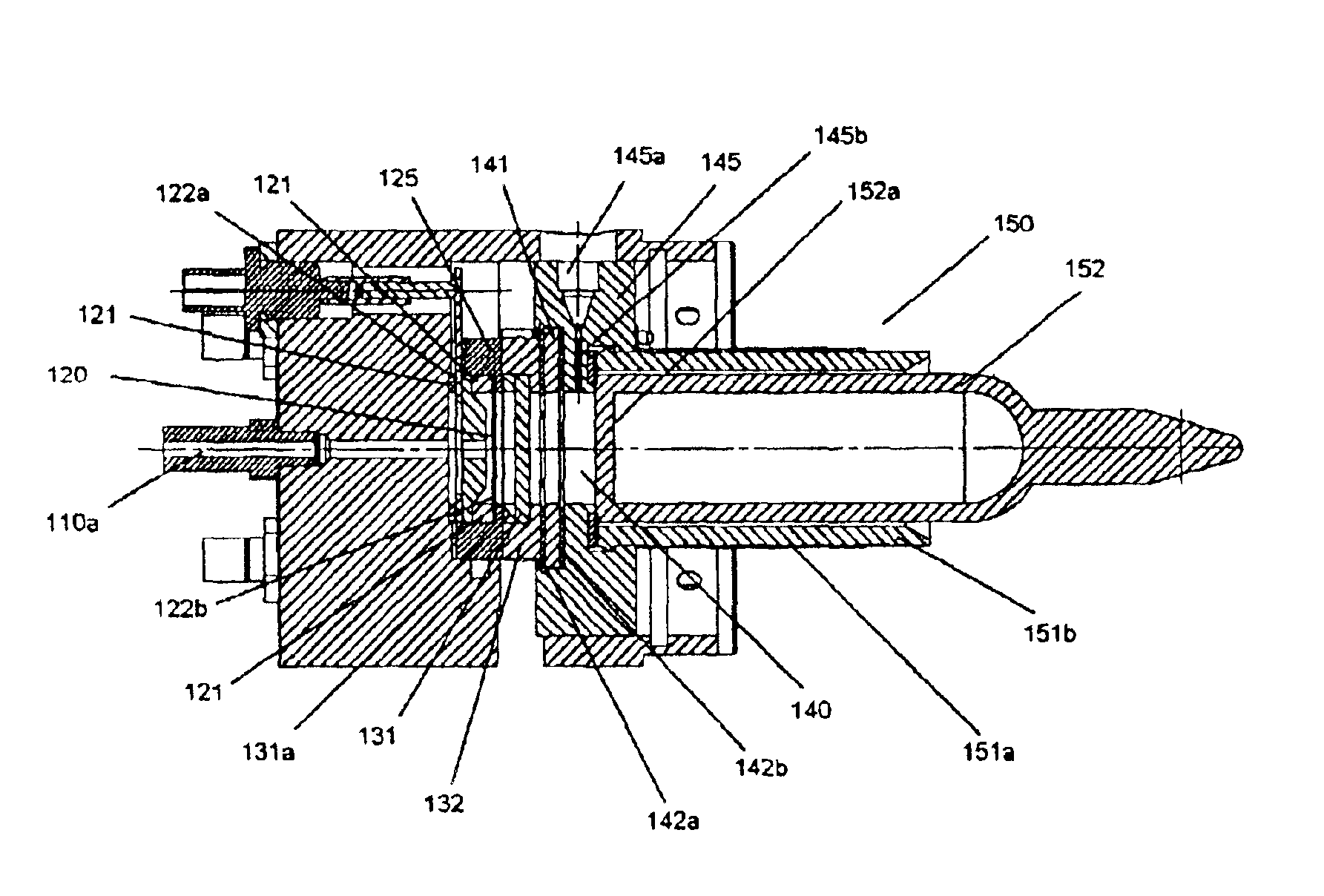
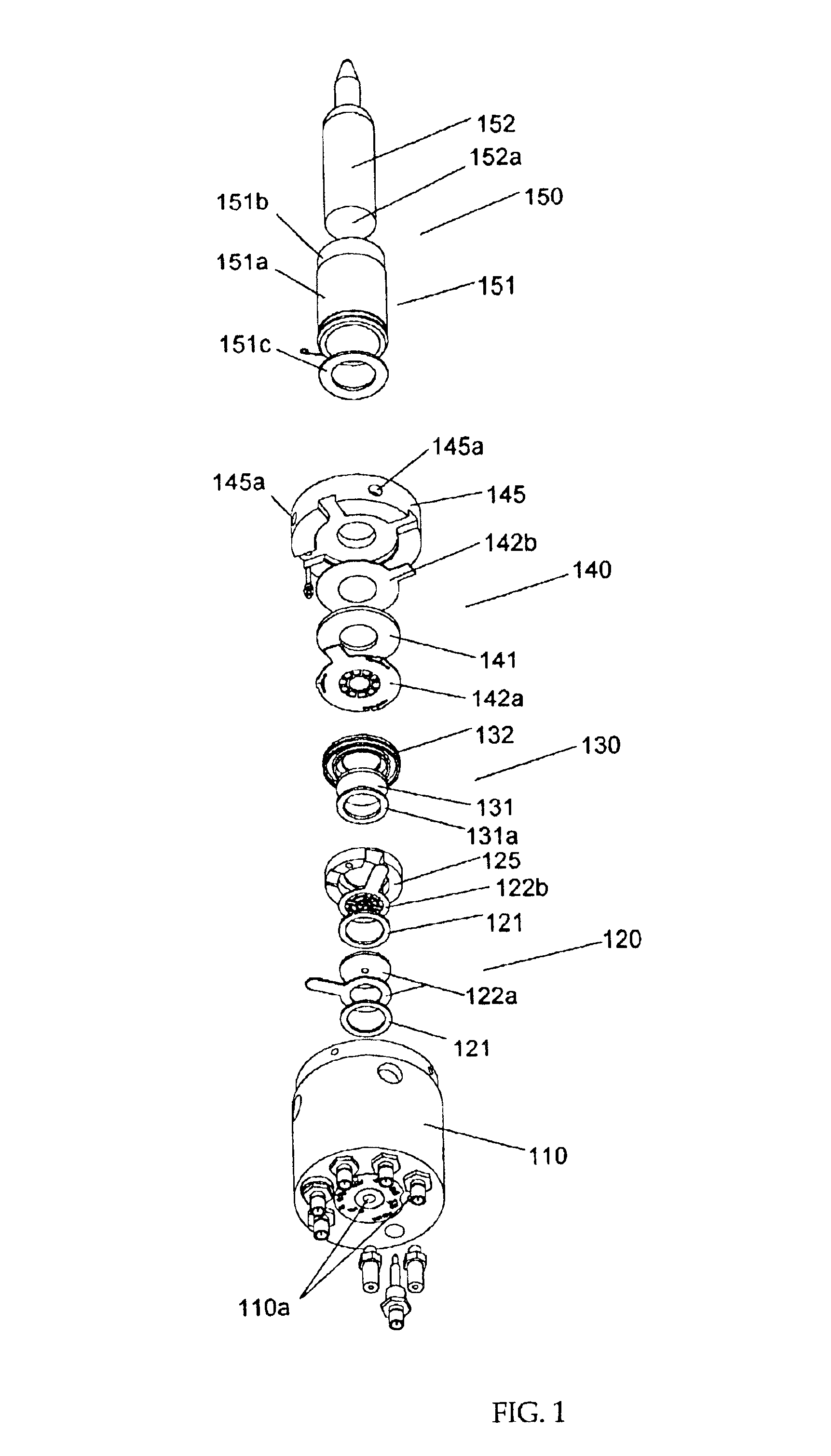
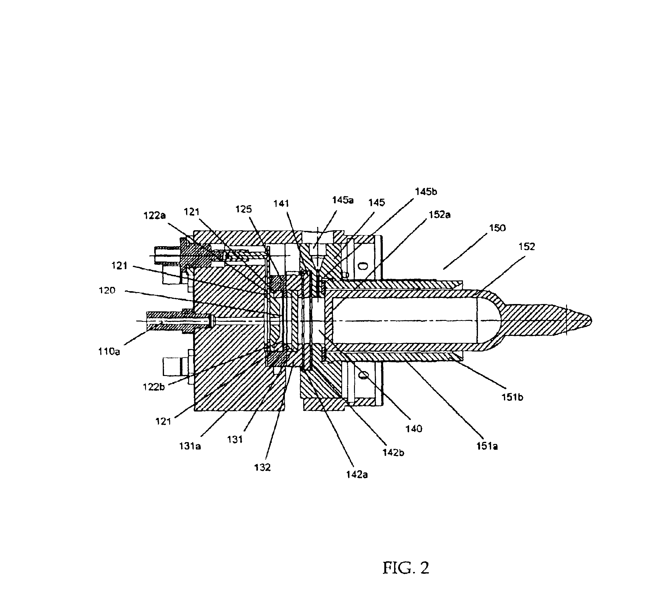
FIG. 1 shows an exploded view and FIG. 2 shows a sectional view of a photoionization detector in accordance with an embodiment of this invention. Detector housing 110 holds a first ionization cell 140, a window assembly 130, a second ionization cell 120, and an ultraviolet (UV) radiation source 150.

In one embodiment, UV radiation is generated by a UV lamp 152. The UV lamp body is made of glass and is filled with krypton, argon, xenon, or helium and a UV lamp window 152a on the end of the lamp, the UV lamp window 152a made of a material that is transmissive of UV radiation such as magnesium fluoride, lithium fluoride, barium fluoride, strontium fluoride, calcium fluoride or sapphire. The lamp is placed in a radio frequency (RF) inductive coupler 151 that is comprised of a RF holder 151b made of polytetrafluoroethylene (PTFE) and an inductive coupler coil 151a wound around the RF holder 151b, the inductive coupler coil 151a being connected at one end to an RF oscillator circuit. Excit...


PUM


Abstract

A photoionization detector comprising multiple ionization cells for detecting the presence of chemical compounds in multiple fluid samples. The photoionization detector uses a single source of ultraviolet (UV) radiation to emit high energy photons into at least two ionization cells. Each ionization cell comprises at least one fluid inlet and at least one fluid outlet. Independent samples of fluid can be introduced into each cell and exposed to the UV radiation such that any molecules with an ionization energy lower that the energy of the photons are ionized. Each ionization cell also comprises a set of at least two electrodes arranged to generate an electric field such that ionized molecules are attracted to the electrode at lower voltage potential resulting in an electrical current.

Description

BACKGROUND OF THE INVENTION1. Field of the InventionThe present invention is related to photoionization detectors for detecting the presence of chemical compounds in a fluid and more particularly to a photoionization detector that comprises multiple ionization cells.2. Description of the Background ArtPhotoionization detectors (PIDs) are conventionally used to detect the presence of chemical compounds in air. When a molecule is exposed to high-energy photons of the appropriate photon energy, the molecule will become ionized. A pair of electrodes are arranged to be exposed to the ionized molecule such that the electrodes are electrically insulated from each other and are maintained at a voltage differential from each other. The ion is repelled from the higher voltage electrode and attracted to the lower voltage electrode. When a fluid stream is exposed to the high-energy photons, and a number of ions are produced, a measurable current is generated.Conventionally, a PID that is used i...

Claims


Application Information

Patent Timeline
IPC IPC(8): G01N27/66G01N30/72G01N30/00G01N27/64
CPCG01N30/7206G01N27/66
Inventor KOLAJA, ROBERT J.BARKER, NICHOLAS J.RAUBVOGEL, ORI D.
Owner KOLAJA ROBERT J
Learn More