
Brushless motor control method

Inactive Publication Date: 2005-01-04
MITSUBA CORP
View PDF6 Cites 15 Cited by
  • Summary
  • Abstract
  • Description
  • Claims
  • Application Information

AI Technical Summary

Benefits of technology

In view of the above identified circumstances, it is therefore an object of the present invention to reduce the torque ripple in a brushless motor whose driving direction is frequently switched from forward drive to backward drive and vice versa and whose acceleration can change to a large extent.
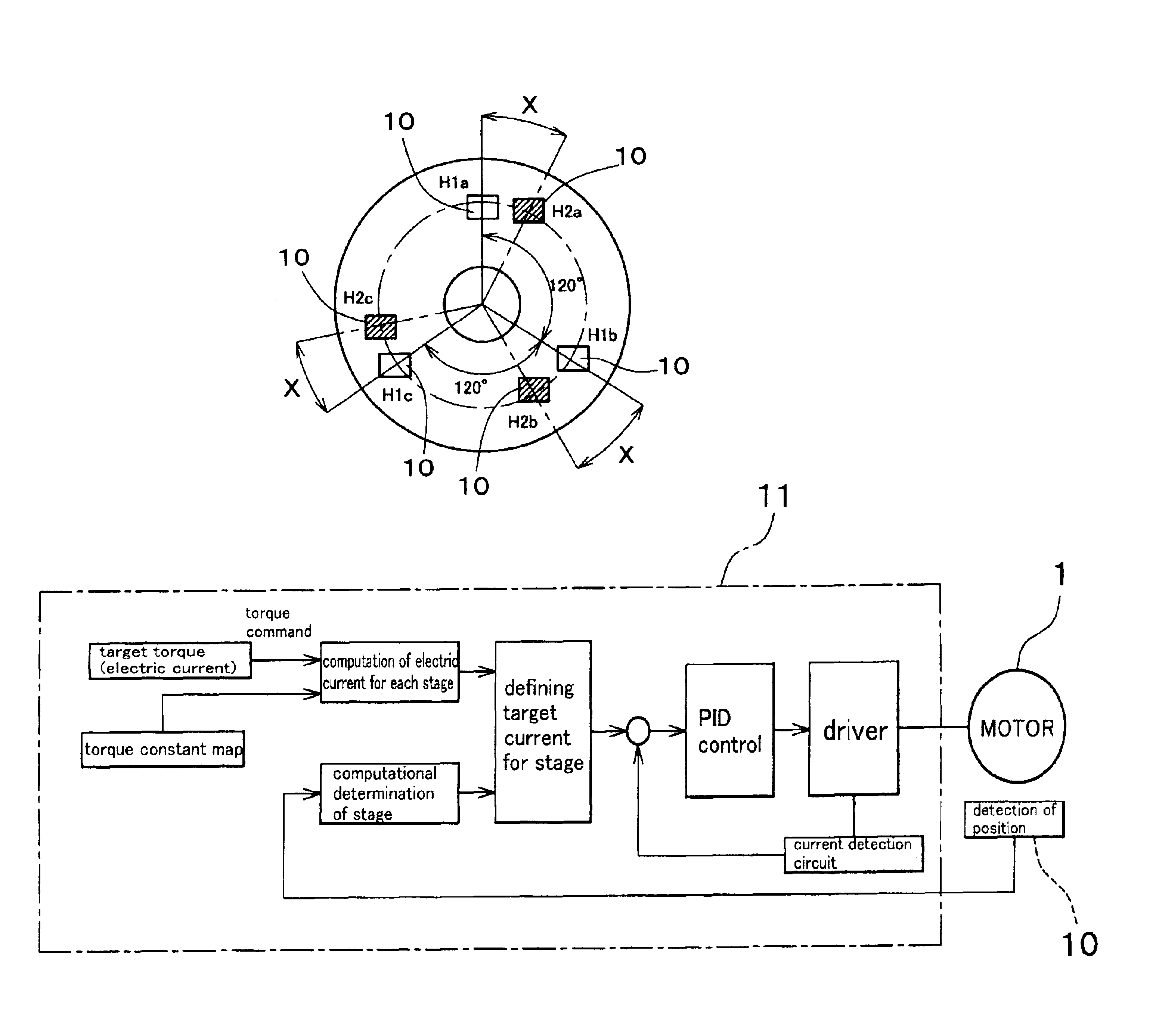
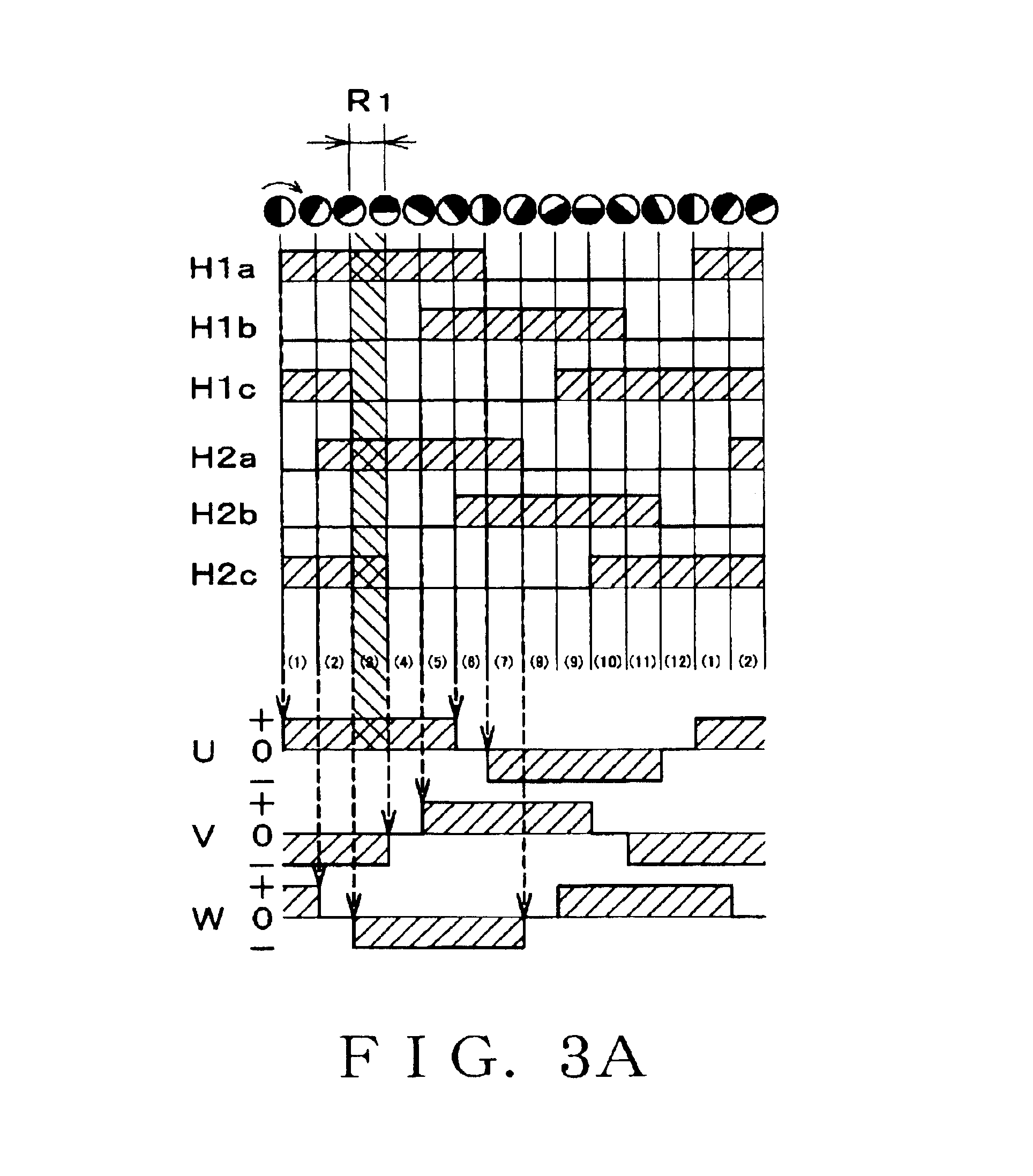
In a control method according to the invention, it may be so arranged that excitation phases of the same polarity are formed in an overlapping way for commutation on the basis of the outcome of the detection of rotary positions of the rotor by means of the first and second sensor groups. With this arrangement, the overlapping energization can be conducted without involving estimates while doubling the number of control stages. Therefore, the torque ripple can be reduced in an operating environment where forward revolutions and backward revolutions are switched from one to the other fiercely and the resultant acceleration changes greatly.

Problems solved by technology

For example, the motors that are used in electric power steering apparatuses are required to reduce the torque ripple because it adversely affects the feeling of the driver steering the automobile to a large extent.
This problem is serious particularly when the valve is closing.
However, when a resolver is used as unit in a brushless motor, it is expensive and a dedicated R / D converter (resolver signal / digital signal converter) has to be installed as interface with the corresponding control unit.
Therefore, a motor using a resolver is accompanied by a problem of high cost of the entire system.
However, in the case of conventional systems for driving 3-phase brushless motors by using three magnetic detection elements, the accuracy of detection of the rotor position is poor and a rectangular drive mode has to be employed so that consequently it is difficult to reduce the torque ripple.
However, in the case of an electric power steering apparatus or an electronically controlled throttle valve, forward revolutions and backward revolutions are switched from one to the other fiercely as the steering apparatus is operated or the throttle valve is opened or closed and the resultant acceleration changes greatly.
Additionally, the steering operation and the accelerating operation can remarkably differ in individuals and some can steer and accelerate the car in a highly abrupt manner.
Therefore, it is difficult to accurately predict the behavior of the motor.
It is also difficult to predict the behavior of the motor when the motor speed is low and / or the motor is being accelerated.
Thus, the rotary position of the rotor estimated by means of a timer or a piece of software can involve a large error and hence the overlapping energization cannot be conducted at appropriate timings.
However, it is difficult to adopt overlapping energization for electric power steering apparatuses and electronically controlled throttle valves.
Therefore, a highly expensive resolver has to be used for such motors to raise the cost of the motor.

Method used


Image

  • Brushless motor control method
  • Brushless motor control method
  • Brushless motor control method

Examples


Embodiment Construction

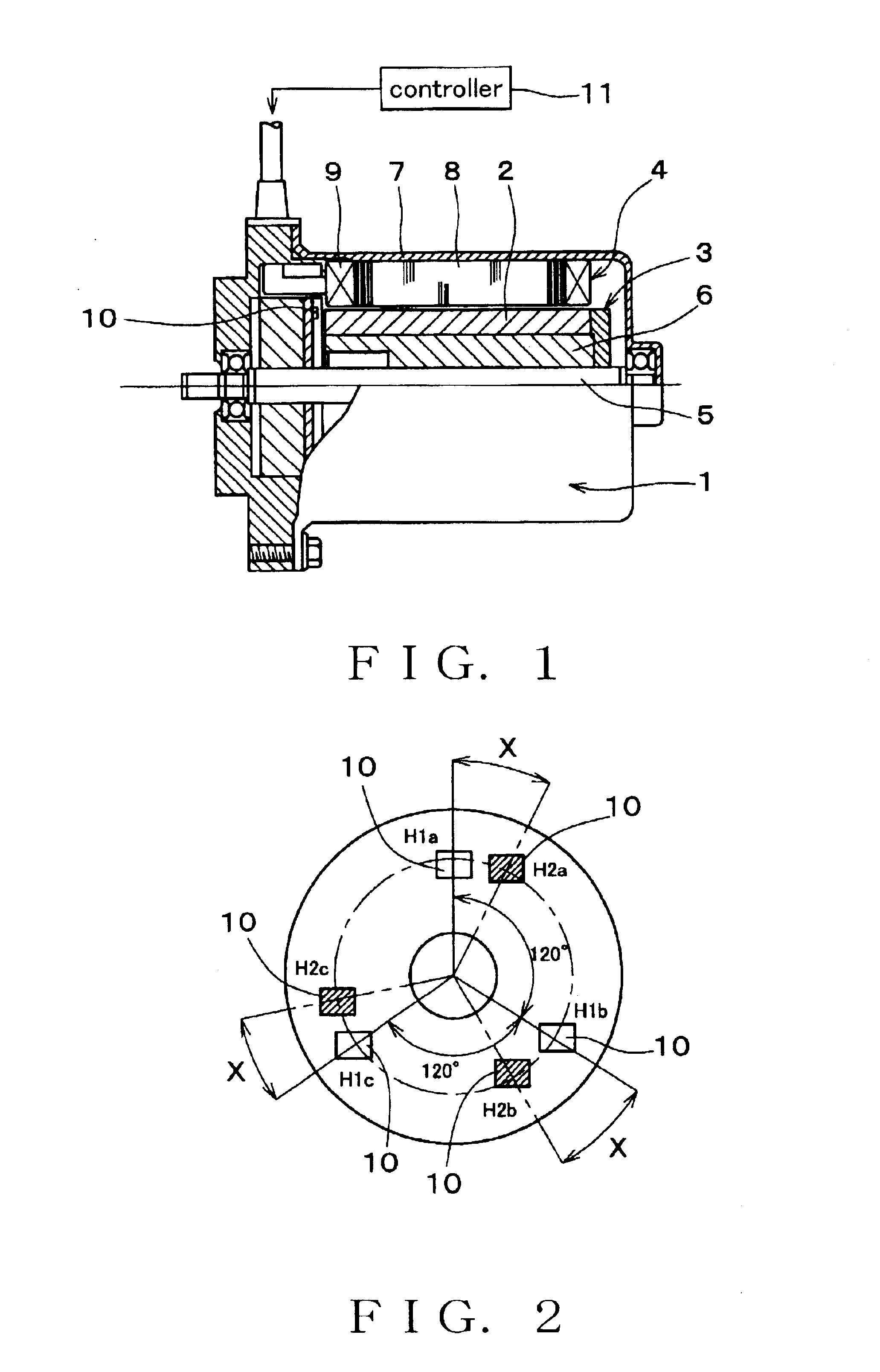
Now, the present invention will be described by referring to the accompanying drawings that illustrate an embodiment of the invention. FIG. 1 is a schematic illustration of an embodiment of brushless motor 1 (to be referred to as motor 1 hereinafter) according to the invention, showing its configuration. The motor 1 is used as a drive source of an electric power steering apparatus. As shown in FIG. 1, the motor 1 has a configuration of that of an inner rotor type motor, in which a stator 4 is arranged around a rotor 3 having a rotor magnet 2 (permanent magnet to be referred to as magnet 2 hereinafter). As a driver operates a steering wheel, the motor 1 is driven under control in accordance with a steering angle, a driving speed of a vehicle and other factors and steering assistance force is supplied to a steering column by way of a reduction apparatus (not shown).

The rotor 3 has a rotor core 6 fitted to a metal shaft 5 and a bipolar magnet 2 rigidly secured to the outer periphery of...


PUM


Abstract

Energization stages are formed by first and second sensor groups and a torque constant is defined for each of the stages. A target current value is computationally determined so as to drive a motor under control. As a torque command showing a target torque of the motor is input to the controller, the target current value is computationally determined for each stage according to a torque constant map, which provides a table of torque constants for different phases and different stages. The rotor angle of the motor is detected by Hall sensors and the current stage is computationally determined on the basis of the detected rotor angle. Then, a target current value is defined as a function of the target torque for each stage on the basis of the current stage and the motor is driven by the driver under PID control based on the target current value.

Description

BACKGROUND OF THE INVENTION1. Field of the InventionThis invention relates to a method of controlling a brushless motor. More particularly, the present invention relates to a technique that can be effectively applied to a brushless motor to be used for an electric power steering apparatus or an electronically controlled throttle valve.2. Related Art StatementTorque ripples have been an important problem that needs to be resolved. Torque ripples have to be reduced in order to achieve a low vibration level and a low noise emission level for brushless motors. For example, the motors that are used in electric power steering apparatuses are required to reduce the torque ripple because it adversely affects the feeling of the driver steering the automobile to a large extent. Similarly, the motors that are used in electronically controlled throttle valves of engines are required to reduce the torque ripple from the viewpoint of engine control because it influences the opening / closing operat...

Claims


Application Information

Patent Timeline
IPC IPC(8): H02P6/10H02P6/00H02P6/08H02P6/06B62D5/04H02P6/28
CPCH02P6/10H02P6/002H02P6/28
Inventor SHINDO, YOICHI
Owner MITSUBA CORP
Learn More