Electromechanical wheel brake device

a technology of electromechanical and wheel brake, which is applied in the direction of braking system, synchronous motor, magnetic circuit shape/form/construction, etc., can solve the problems of reducing the effort and cost involved in manufacturing, not being able to accommodate or mount a large number of coils, and the attachment of coils and their attachmen

Inactive Publication Date: 2004-10-19
ROBERT BOSCH GMBH
View PDF14 Cites 31 Cited by
  • Summary
  • Abstract
  • Description
  • Claims
  • Application Information

AI Technical Summary

Benefits of technology

The invention is an improved electromechanical wheel brake device that uses a transverse flux motor to generate braking force. The motor has a single excitation winding that drives a nut of a rotation / translation conversion gear, which is connected to a brake disk non-rotatably connected to a vehicle wheel. The motor has a stator with yokes and poles, and the poles are magnetized by supplying current to the excitation winding. The motor has a high power density and increased motor dynamics, and it can be designed with a large number of poles without increasing manufacturing costs. The motor can be placed in an annular design, and the rotation / translation conversion gear and reduction gear can be accommodated inside the motor. The invention reduces the effort and cost involved in manufacturing and improves the efficiency, volume reduction, and power density of the wheel brake device.

Problems solved by technology

Since the winding of coils and their attachment to the poles and yokes is expensive, this reduces the effort and cost involved in manufacturing.
An increase in the number of poles therefore does not increase the manufacturing costs or only increases them slightly; the problem of not being able to accommodate or mount a large number of coils does not occur.
In addition, situating the electric motor in an annular fashion around the gear produces a large lever arm and therefore a high driving torque of the electric motor.

Method used


Image

  • Electromechanical wheel brake device
  • Electromechanical wheel brake device
  • Electromechanical wheel brake device

Examples


Embodiment Construction

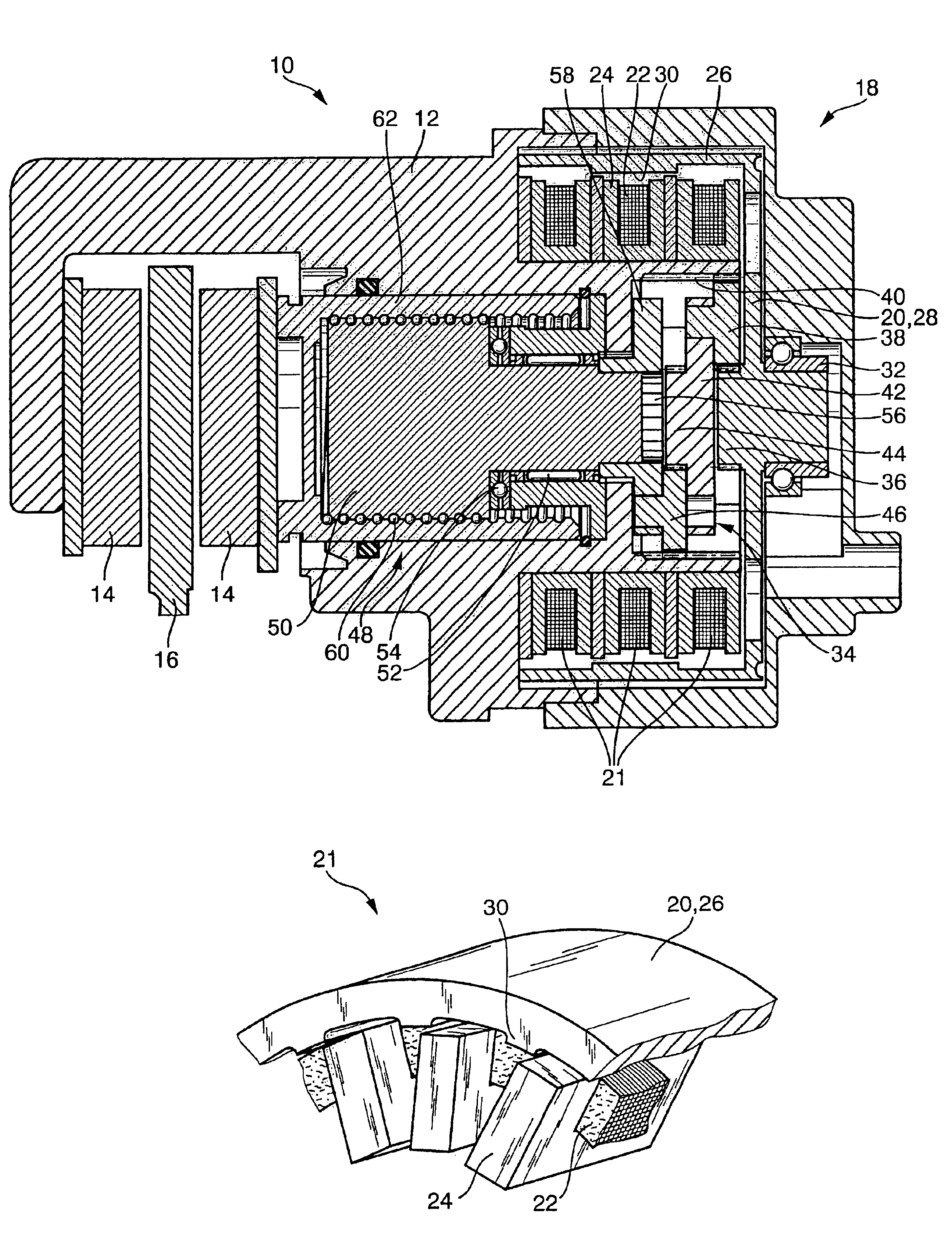
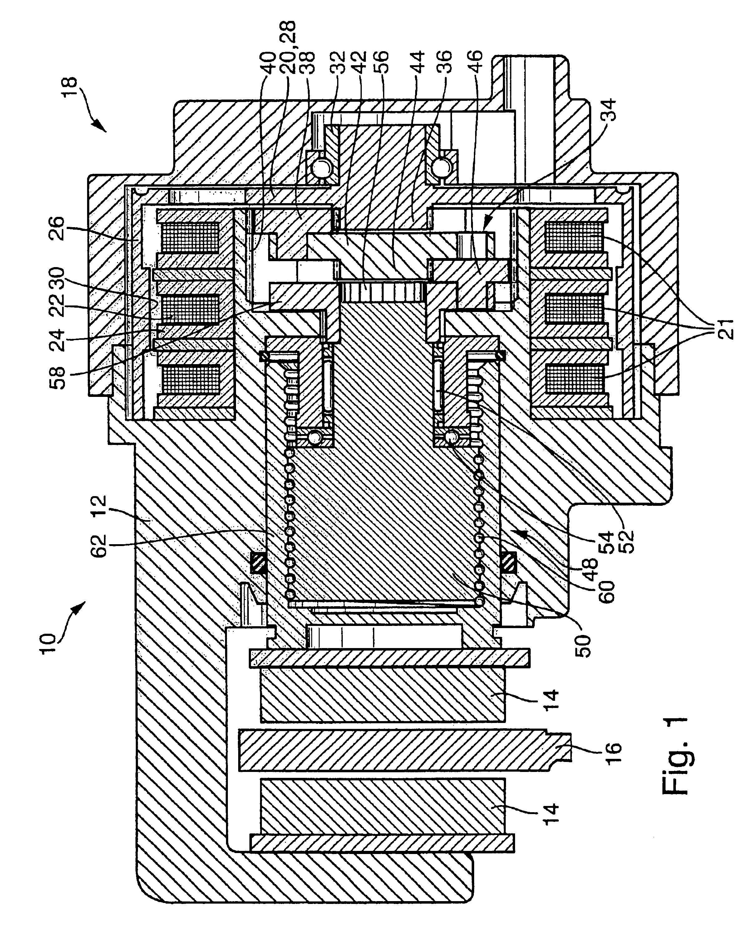
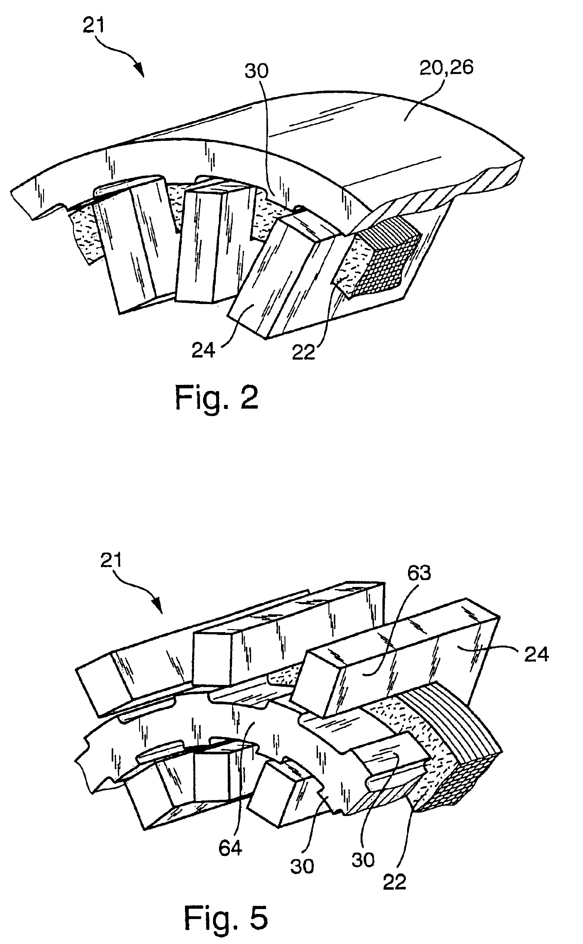
In order to avoid repetition, only to differences between the electromechanical wheel brake device 10 according to the invention shown in FIG. 3 and the wheel brake device 10 shown in FIG. 1 will be explained. Otherwise, please refer to the explanations made in conjunction with FIG. 1. Parts, which are the same, are provided with the same reference numerals. In the wheel brake device 10 shown in FIG. 3, the transverse flux motor 18 is embodied differently than in FIG. 1. The transverse flux motor 18 in FIG. 3 is likewise embodied as a hollow shaft motor, but is designed as a so-called internal rotor motor. In the transverse flux motor 18 shown in FIG. 3, the excitation device 22, 24 with the excitation winding 22 and the U-shaped yokes 24 is disposed outside the likewise cup-shaped rotor 20. The U-shaped yokes 24 are therefore placed onto the excitation winding 22 from the outside, the opening of the yokes 24 points radially inward toward the cylindrical circumference wall 22 of the...


PUM


Abstract

The invention relates to an electromechanical wheel brake device, with an electric motor that can press a frictional brake lining against a brake body (brake disk) by a reduction gear (planetary gear) and a rotation / translation conversion gear (ball screw). The invention proposes embodying the electric motor as a transverse flux motor with three phase windings; each phrase winding has a circular, annular excitation winding that is disposed inside U-shaped yokes, which are distributed over the circumference of the excitation winding. This embodiment of the electric motor permits a compact design of the electric motor in an annular, hollow shaft design so that the reduction gear and the rotation / translation conversion gear can be disposed at least partially inside the electric motor.

Description

1. Field of the InventionThe invention relates to an improved electromechanical wheel brake actuating device.2. Description of the Prior ArtA wheel brake device of the type with which this invention is concerned has been disclosed by WO 96 / 03301. The known wheel brake device has an electric motor with an annular rotor, which can rotatingly drive a nut of a rotation / translation conversion gear embodied as a helical gear. The rotation / translation conversion gear converts the rotatory drive motion of the electric motor into a translatory motion so that a frictional brake lining of the wheel brake device can be pressed against a rotating brake body in order to generate a braking force or a braking moment. In order to release the wheel brake device, the frictional brake lining can be lifted up from the brake body by rotating the electric motor in the opposite direction. The known wheel brake device is embodied as a disk brake, the brake body is a brake disk non-rotatably connected to a v...

Claims


Application Information

Patent Timeline
Patent Type & Authority Patents(United States)
IPC IPC(8): B60T13/74B60T13/00F16D65/14H02K7/06H02K37/02H02K37/04H02K19/02H02K19/10F16D65/18
CPCB60T13/741F16D65/18H02K37/04H02K7/06H02K19/103F16D2121/24F16D2125/40F16D2127/06F16D2125/50B60T13/74
Inventor HILZINGER, JUERGENSCHUMANN, FRANKBLOSCH, GEORGKASTINGER, GUENTER
Owner ROBERT BOSCH GMBH
Why Eureka
Try Eureka