
Group delay equalizer integrated with a wideband distributed amplifier monolithic microwave integrated circuit

a technology of amplifier monolithic microwave and equalizer, which is applied in the direction of waveguide type devices, line-transmission details, baseband system details, etc., can solve the problems of data pulse distortion, delay is not constant, and the signal is appreciably distorted

Inactive Publication Date: 2004-10-05
REMEC DEFENSE & SPACE INC +1
View PDF17 Cites 8 Cited by
  • Summary
  • Abstract
  • Description
  • Claims
  • Application Information

AI Technical Summary

Benefits of technology

The integrated group delay equalizer circuit achieves near-constant group delay and flat gain over a broad frequency range, reducing signal distortion and improving signal-to-noise ratio, and reducing data bit errors in high-data-rate electro-optics systems, while minimizing the increase in MMIC size and cost.

Problems solved by technology

If uncorrected, this difference in time delay may give rise to appreciable distortion of the signal.
However, if the phase shift does not increase linearly with frequency, the time delay varies with frequency, and thus the group delay is not constant over all frequencies.
Although such previous optical systems have experienced problems resulting from group delay variation within the amplifier itself, with higher data rates (40 Gbit / s and higher) that produce short data pulses, any group delay variation within the amplifier itself may result in distortion of the data pulse.
Although this enables low distortion pulse amplification, the gain rolloff severely restricts the application of the amplifier to other applications, for instance, wideband test equipment, or radios, where constant gain versus frequency amplification is preferred.
However, the external group delay equalizer, typically fabricated as a thin-film network, may be larger than the distributed amplifier monolithic microwave integrated circuit, which adds loss to the overall circuit, thereby reducing the overall amplifier gain.
In addition, the increased area of the overall circuit due to the external group delay equalizer is also a disadvantage for densely packed transceivers.

Method used


Image

  • Group delay equalizer integrated with a wideband distributed amplifier monolithic microwave integrated circuit
  • Group delay equalizer integrated with a wideband distributed amplifier monolithic microwave integrated circuit
  • Group delay equalizer integrated with a wideband distributed amplifier monolithic microwave integrated circuit

Examples


Embodiment Construction

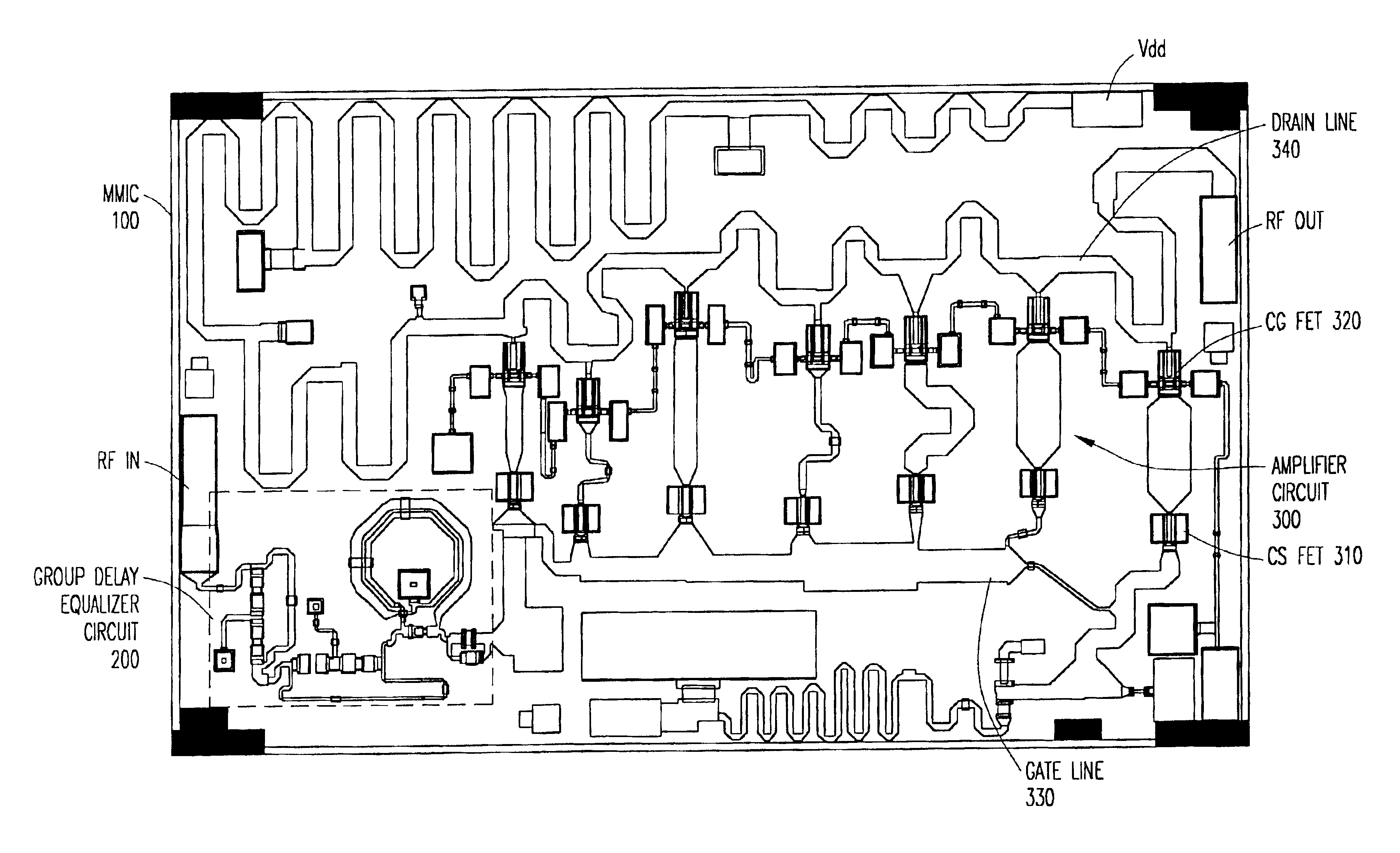
The numerous innovative teachings of the present application will be described with particular reference to the exemplary embodiments. However, it should be understood that these embodiments provide only a few examples of the many advantageous uses of the innovative teachings herein. In general, statements made in the present application do not necessarily delimit any of the various claimed inventions. Moreover, some statements may apply to some inventive features, but not to others.

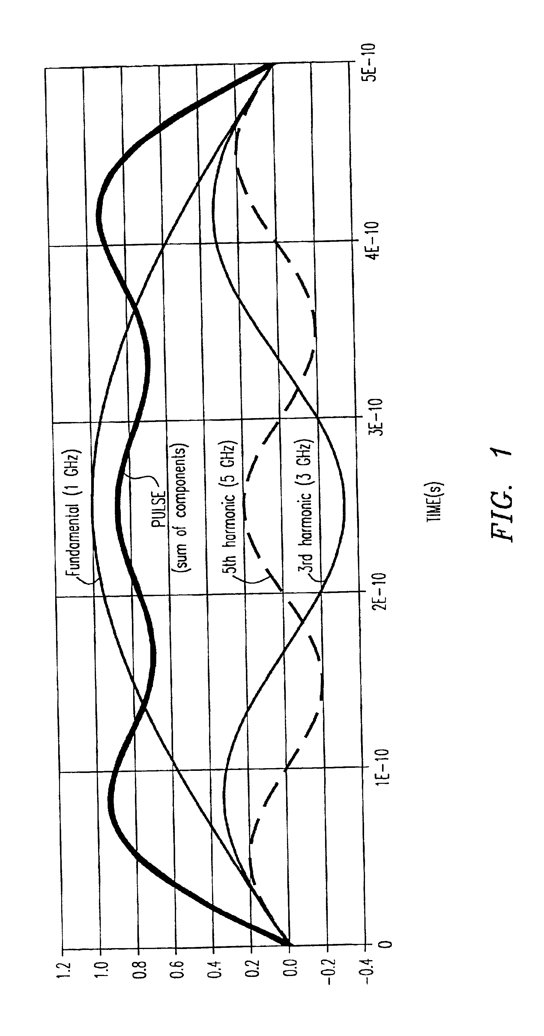
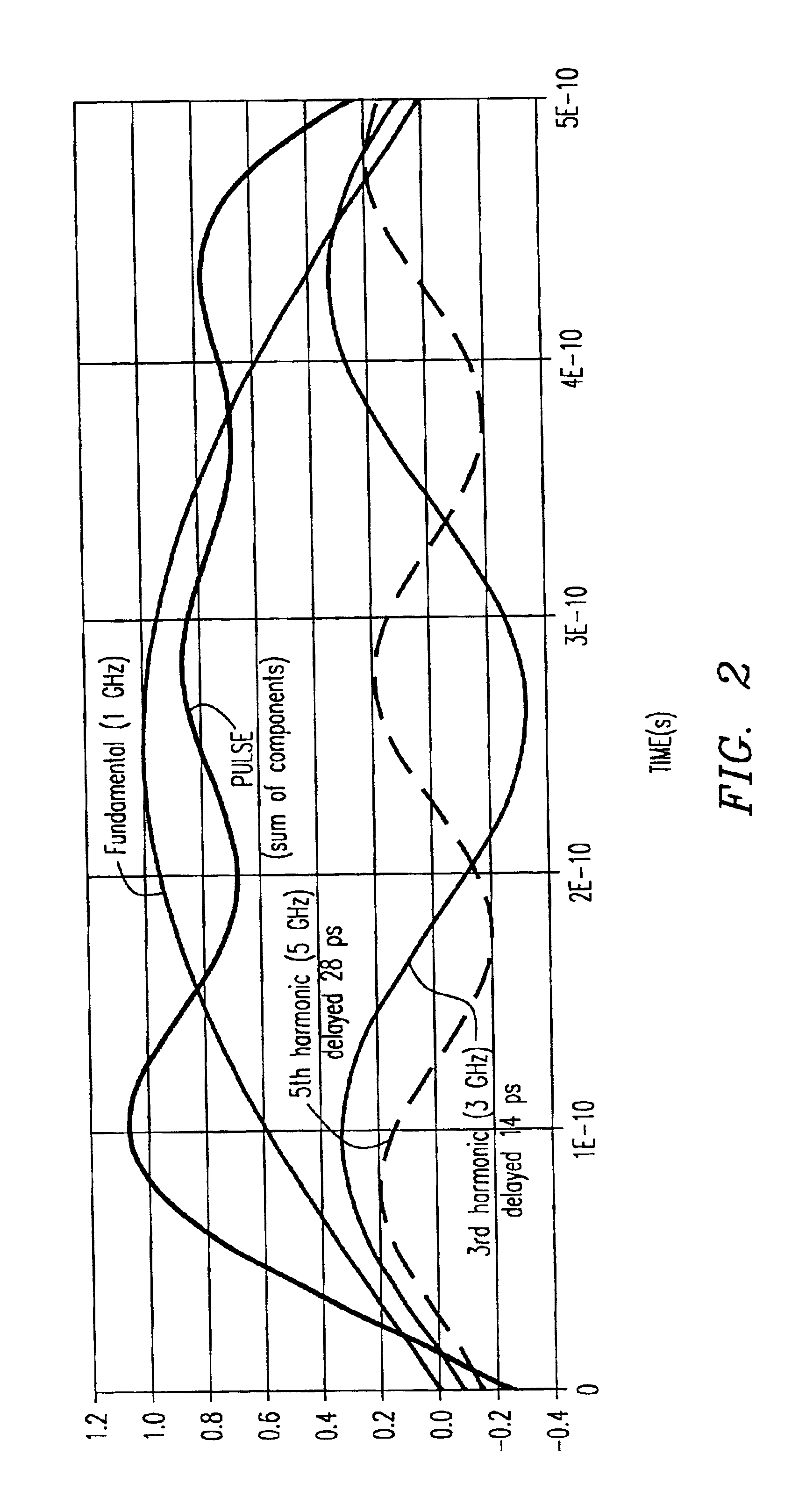
As is understood in the art, a digital pulse is made up of multiple frequency components. If all frequency components are not delayed by the same amount within a circuit, the resulting output signal will be distorted. For example, a near square pulse that is made up of a fundamental carrier at 1 GHz and two harmonics, the 3.sup.rd (3 GHz) and 5.sup.th (5 GHz) harmonics, is shown in FIG. 1. As shown in FIG. 1, when the frequency components sum with constant (same) group delay for each, the resultant wavef...


PUM


Abstract

A wideband distributed or feedback amplifier monolithic microwave integrated circuit (MMIC) is disclosed that contains an integrated group delay equalizer circuit to compensate for the group delay variation of the amplifier circuitry. The MMIC amplifier is capable of achieving a predicted constant group delay with little variation over a wide frequency range. In addition, the group delay equalizer circuit enables the amplifier to achieve flat (constant) gain over a wide bandwidth, while maintaining constant group delay. Furthermore, the group delay equalizer circuitry requires only a small portion of the total MMIC area.

Description

1. Field of the InventionThe present invention relates generally to distributed amplifier monolithic microwave integrated circuits (MMIC's), and specifically to group delay equalizer circuits for distributed amplifier MMIC's.2. Description of Related ArtAs is well-known in the art, electromagnetic waves of different frequencies experience different time delays when transmitted through a transmission system. For example, when a broadband microwave signal is transmitted through a waveguide, the lower frequency components are delayed to a different extent than the higher frequency components. If uncorrected, this difference in time delay may give rise to appreciable distortion of the signal.The time delay present in a circuit is known as the group delay of the circuit. Group delay is a measure of the rate of change (derivative) of amplifier phase versus frequency. Group delay remains constant over a frequency range if the insertion phase (phase shift) changes linearly with frequency. F...

Claims


Application Information

Patent Timeline
Patent Type & Authority Patents(United States)
IPC IPC(8): H03F3/60
CPCH03F3/602H03F3/60
Inventor OZAWA, KAZUYAYOK, SAPHANNELSON, STEPHEN R.
Owner REMEC DEFENSE & SPACE INC
Learn More