
Method for stabilizing properties of a ferromagnetic tunnel junction element

a technology properties, which is applied in the direction of electrical transducers, record information storage, instruments, etc., can solve the problems of acceleration of stabilization, deformation of reproducing output, and decrease of resistance of ferromagnetic tunnel junction elements

Inactive Publication Date: 2004-08-03
TDK CORPARATION
View PDF9 Cites 11 Cited by
  • Summary
  • Abstract
  • Description
  • Claims
  • Application Information

AI Technical Summary

Benefits of technology

The above step short-circuits electrically (breaks-down softly) thinner parts of the insulating film as the tunnel barrier layer in the ferromagnetic tunnel junction element in advance, and thereby, can stabilize the resistance of the insulating film at its practical operation. Therefore, the stabilizing method of the present invention can repress the property fluctuation of the ferromagnetic tunnel junction element at the practical operation thereof. The stabilizing method decreases the output power of the ferromagnetic tunnel junction element slightly, but the decrease degree of the output power is negligible at the practical operation of the ferromagnetic tunnel junction element.
It is desired that the current to be supplied in the above stabilizing step is larger than that in the practical operation, which can reduce the stabilizing time. A current generator can supply the above current in the stabilizing process.
Moreover, the stabilizing step is preferably carried out at room temperature or over, which results in the acceleration of the stabilization and thereby, the shortening of the stabilizing time. However, it is desired that the stabilizing temperature is 300.degree. C. or below. If the stabilizing temperature is more than 300.degree. C., the ferromagnetic tunnel junction element is thermally damaged, so that its TMR (tunnel magnetoresistive effect) variation ratio is decreased extremely.
The current value to be supplied in the stabilizing step is determined on the current supplying time. That is, a large current can shorten the current supplying time and a small current requires a long current supplying time.
The stabilizing method of the present invention can be also applied for a wafer having many aligned thin film magnetic head elements. In this case, the wafer is improved a little. Concretely, the ferromagnetic tunnel junction elements, each included in each of the thin film magnetic head elements, are in series connected successively, and turned on electricity during a given period. To connect the ferromagnetic tunnel junction elements in series, two terminals of each element are connected successively by conductors. According to the present invention, the stabilization for the ferromagnetic tunnel junction elements can be efficiently carried out. The stabilizing step may be performed in any manufacturing step of the thin film magnetic head elements on the wafer, but is preferably done in the last manufacturing step.

Problems solved by technology

In using the above ferromagnetic tunnel junction element as a reading element in a thin film magnetic head, however, it is found that the resistance of the ferromagnetic tunnel junction element is decreased with practical operation time, and thus, the reproducing output is degraded.
Moreover, the stabilizing step is preferably carried out at room temperature or over, which results in the acceleration of the stabilization and thereby, the shortening of the stabilizing time.
That is, a large current can shorten the current supplying time and a small current requires a long current supplying time.
If a voltage more than 2V is applied, the insulating film constituting the tunnel barrier layer may be destroyed.

Method used


Image

  • Method for stabilizing properties of a ferromagnetic tunnel junction element
  • Method for stabilizing properties of a ferromagnetic tunnel junction element
  • Method for stabilizing properties of a ferromagnetic tunnel junction element

Examples


example 1

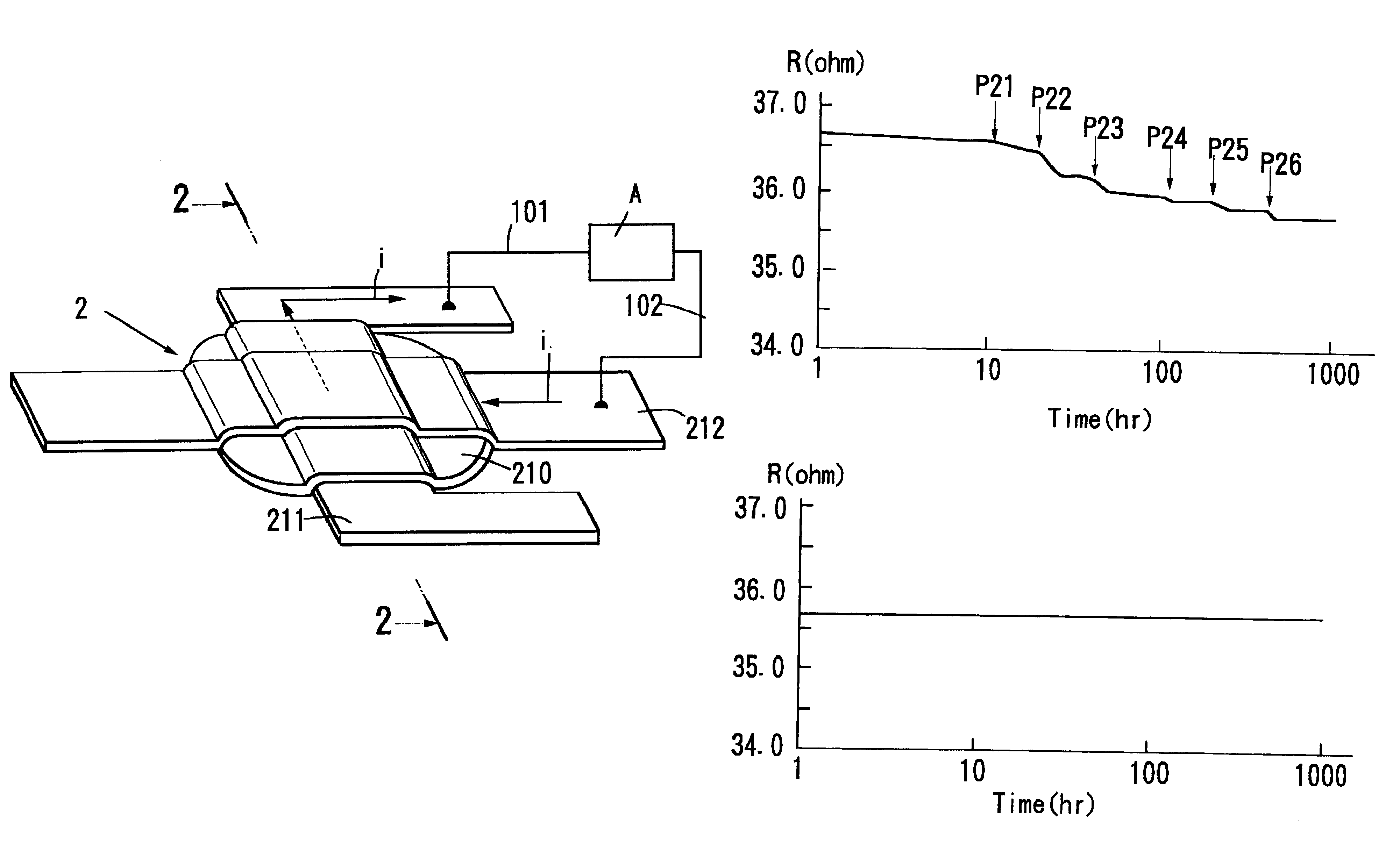
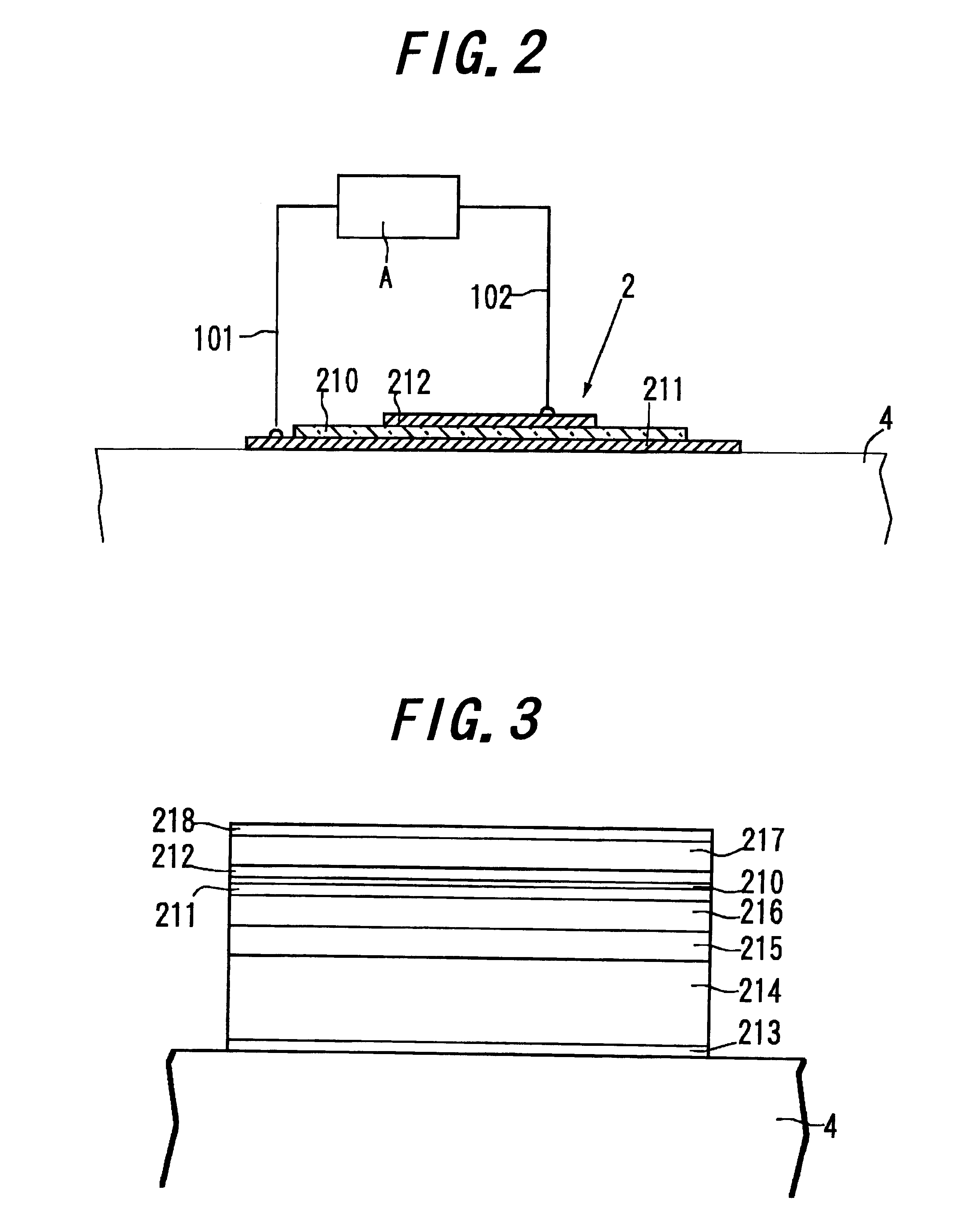
The TMR element having the film structure in FIG. 3 was turned on electricity by a current with 7 mA larger than the above current with 1 mA, which is supposed to be applied in its practical operation, for 1000 hours at 70.degree. C. as its practical operation temperature. In this case, such a wire connection as in FIGS. 1 and 2 was employed.

FIG. 5A shows the obtained experimental data. The axis of abscissas and the axis of ordinate have the same scale as in FIG. 4. As shown in FIG. 5A, three soft break-downs P21 to P23 occur during the turning on electricity for 10-100 hours, and three soft break-down P24 to P26 occur during the turning on electricity for 100-1000 hours. The resistance R has a constant value of about 35.7 (ohm) at the turning on electricity of more than 1000 hours.

FIG. 5B shows the experimental data of the stabilized TMR element in FIG. 5A when a current with 1 mA, which is supposed to be flown during practical operation, is supplied. The axis of abscissas and the ...

example 2

The TMR element having the film structure in FIG. 3 was turned on electricity by a current with 7 mA larger than the above current with 1 mA for 50 hours at 70.degree. C. In this case, such a wire connection as in FIGS. 1 and 2 was employed.

FIG. 6A shows the obtained experimental data. As shown in FIG. 6A, three soft break-downs P31 to P33 occur during the turning on electricity for 10-50 hours.

FIG. 6B shows the experimental data of the stabilized TMR element in FIG. 6A when a current with 1 mA, which is supposed to be flown during practical operation, is supplied. As shown in FIG. 6B, a soft break down occurs in the stabilized TMR element after the turning on electricity for about 1000 hours by the current with 1 mA. That is, in this example, the stabilization for the TMR element is not sufficient.

example 3

The TMR element having the film structure in FIG. 3 was turned on electricity by a current with 15 mA larger than the above current with 1 mA for 24 hours at 70.degree. C. In this case, such a wire connection as in FIGS. 1 and 2 was employed.

FIG. 7A shows the obtained experimental data. As shown in FIG. 7A, several soft break-downs occur during the turning on electricity for 24 hours.

FIG. 7B shows the experimental data of the stabilized TMR element in FIG. 7A when a current with 1 mA is supplied. As shown in FIG. 7B, a soft break down does not occur in the stabilized TMR element after the turning on electricity for about 10000 hours by the current with 0.2 mA. This means that larger stabilizing current can shorten the stabilizing time.


PUM

PropertyMeasurementUnit
Angleaaaaaaaaaa
Angleaaaaaaaaaa
Electric potential / voltageaaaaaaaaaa

Abstract

A method of manufacturing a ferromagnetic tunnel junction element, having an insulating film, a first ferromagnetic film and a second ferromagnetic film, including a step of turning the ferromagnetic tunnel junction element on electricity for a given period before a practical operation of the ferromagnetic tunnel junction element, so that a resistance of the insulating film is stabilized.

Description

1) Field of the InventionThis invention relates to a method for stabilizing properties of a ferromagnetic tunnel junction element, particularly, a method of stabilizing the resistance of an insulating film to divide a first ferromagnetic film and a second ferromagnetic film in the ferromagnetic tunnel junction element.2) Related Art StatementA ferromagnetic tunnel junction element has a junction structure of ferromagnetic film / insulating film / ferromagnetic film. S. Maekawa and V. Gafvert et al. have shown theoretically and experimentally in "IEEE Trans. Magn.", Mag-18, 707 (1982) that the junction structure of ferromagnetic film / insulating film / ferromagnetic film exhibit a ferromagnetic tunnel effect depending on the relative angle of magnetization of both ferromagnetic films. The "ferromagnetic tunnel effect" means the phenomenon that tunnel current to pass through a tunnel barrier layer changes depending on the relative angle of magnetization in both ferromagnetic films of an elem...

Claims


Application Information

Patent Timeline
IPC IPC(8): G01R33/06G01R33/09G11B5/39
CPCB82Y25/00G01R33/093G01R33/098G11B5/3903Y10T29/49034Y10T29/49004Y10T29/49021Y10T29/49036
Inventor SHIMAZAWA, KOJIARAKI, SATORU
Owner TDK CORPARATION
Learn More