Harness routing structure for vehicle
a routing structure and vehicle technology, applied in the direction of insulated conductors, cables, coupling device connections, etc., can solve the problems of high voltage harness breakage, and achieve the effect of shortened life-time of high voltage harnesses
- Summary
- Abstract
- Description
- Claims
- Application Information
AI Technical Summary
Benefits of technology
Problems solved by technology
Method used
Image
Examples
first embodiment
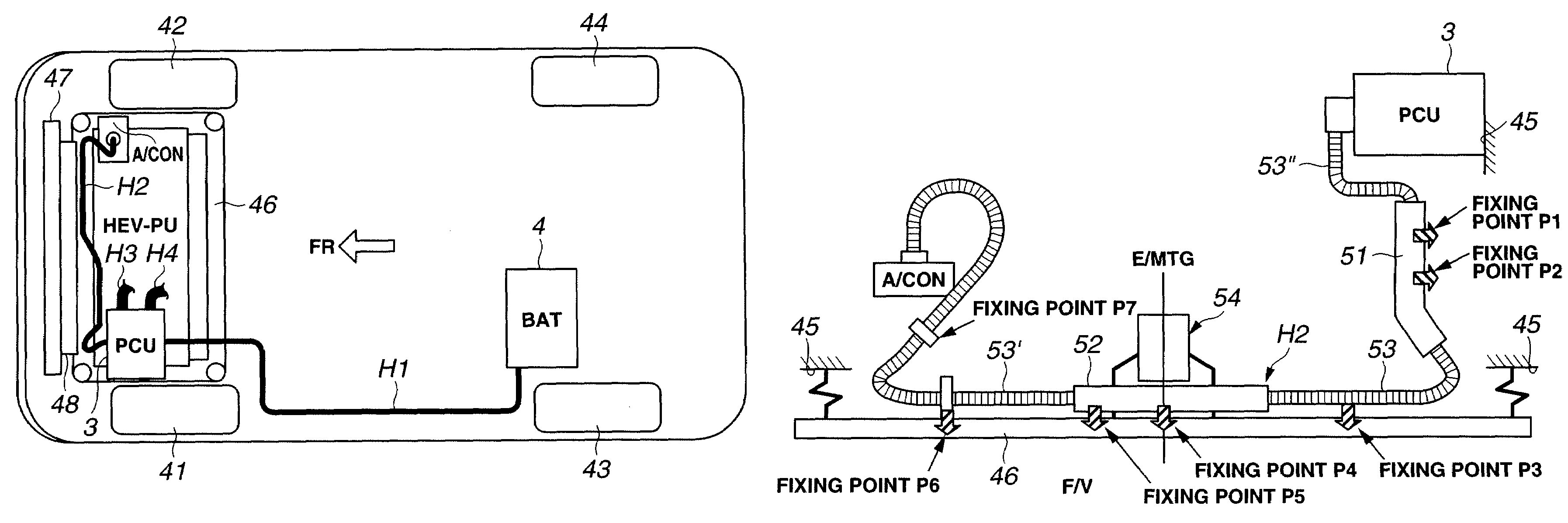
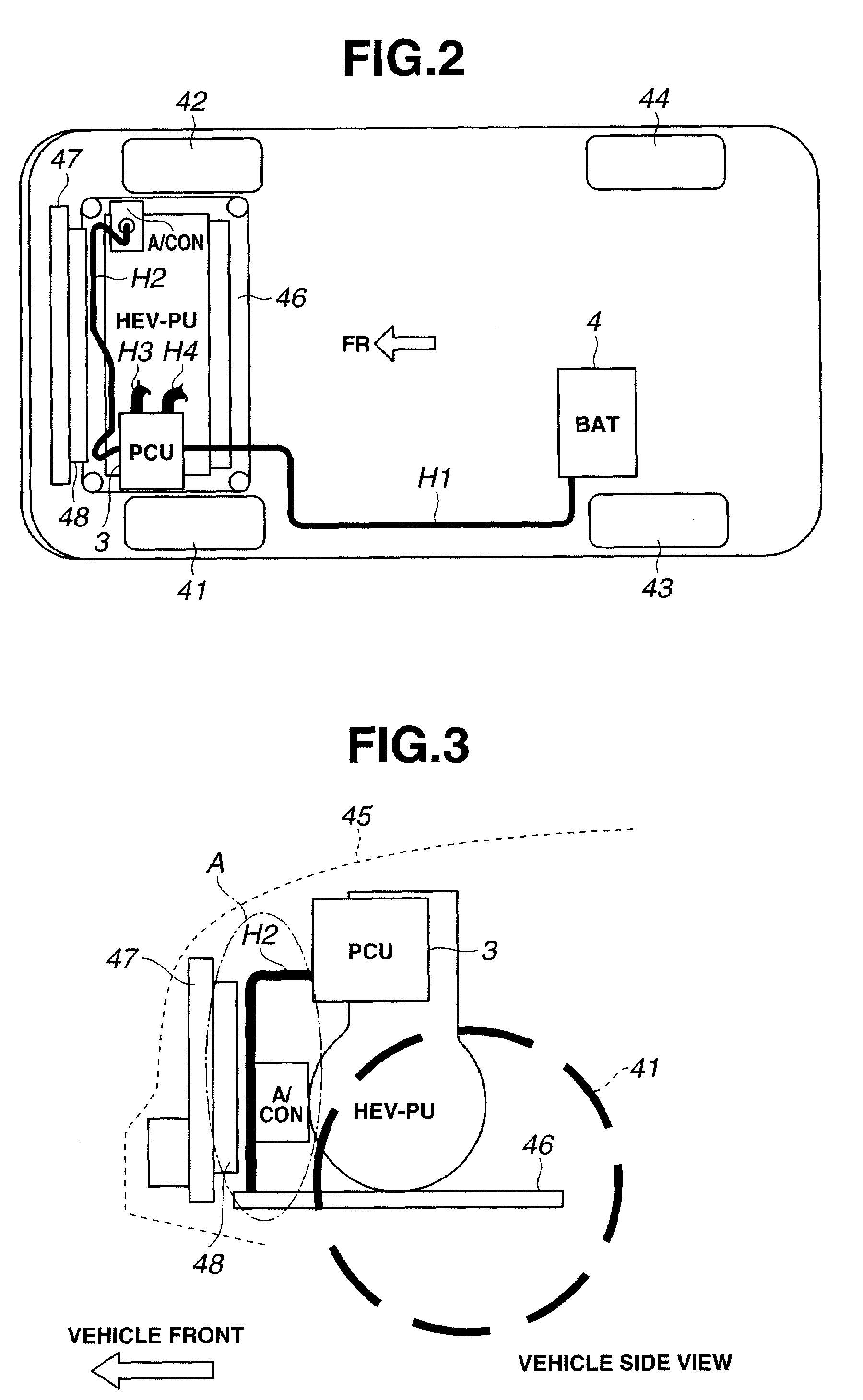
[0040]A configuration of the harness routing structure in the first embodiment will now be explained.
[0041][System Configuration of Hybrid Vehicle]
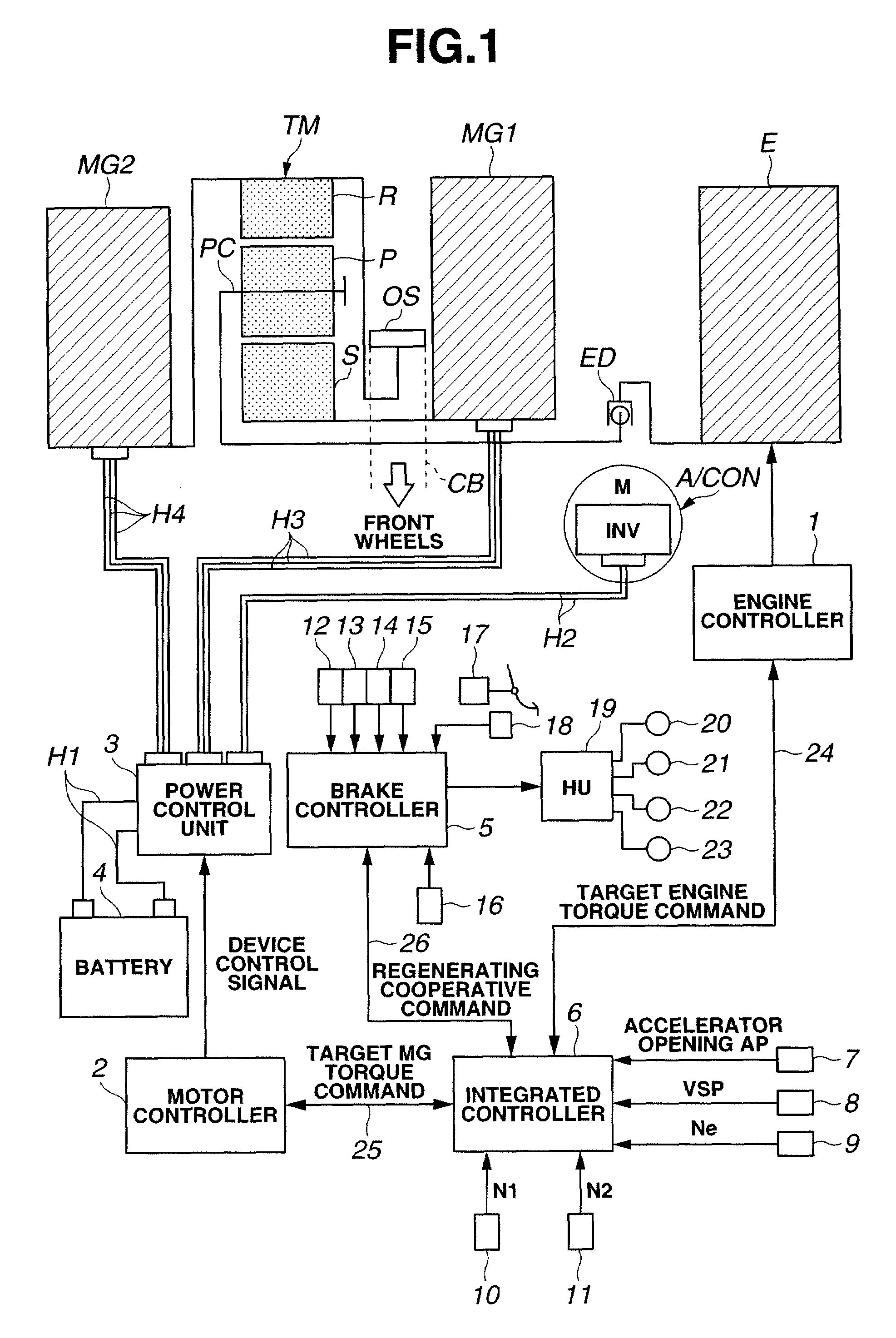
[0042]FIG. 1 is a schematic block diagram showing a drive system of a hybrid vehicle (as one example of vehicle) employing the harness routing structure of the first embodiment. As shown in FIG. 1, the drive system of hybrid vehicle in the first embodiment includes an engine E, a first motor / generator MG1, a second motor / generator MG2, an output sprocket OS, a power (torque) split mechanism TM, and an electrical compressor unit (electrical auxiliary unit) A / CON.
[0043]Engine E is a gasoline engine or diesel engine. Valve opening of a throttle valve of engine E or the like is adjusted according to a control command derived from an engine controller 1 described below.
[0044]Each of first motor / generator MG1 and second motor / generator MG2 is a synchronous-type motor / generator, in which a permanent magnet is set or buried in a rotor and a stato...
PUM
 Abstract
Description
Claims
Application Information
 - R&D
- Intellectual Property
- Life Sciences
- Materials
- Tech Scout
- Unparalleled Data Quality
- Higher Quality Content
- 60% Fewer Hallucinations
Browse by: Latest US Patents, China's latest patents, Technical Efficacy Thesaurus, Application Domain, Technology Topic, Popular Technical Reports.
© 2025 PatSnap. All rights reserved.Legal|Privacy policy|Modern Slavery Act Transparency Statement|Sitemap|About US| Contact US: help@patsnap.com


