
Multi-carrier control method, multi-carrier peak-clipping module and base station

A control method and multi-carrier technology, applied in multi-carrier systems, modulated carrier systems, transmission control/equalization, etc., can solve the problems affecting the stable and reliable operation of base station equipment, increasing power demand of base station power, and decreasing power output capability. , to prevent overloading of the main equipment power supply system, achieve long-term reliable operation, and meet the requirements of design specifications

Active Publication Date: 2009-03-04
HUAWEI TECH CO LTD
View PDF0 Cites 33 Cited by
  • Summary
  • Abstract
  • Description
  • Claims
  • Application Information

AI Technical Summary

Problems solved by technology

Furthermore, it may cause deterioration of indicators such as RF switching spectrum, modulation spectrum and modulation accuracy
In severe cases, it may even cause the multi-carrier power amplifier to burn out
At the same time, if the output power of the multi-carrier power amplifier is too large, it will also increase the power demand of the base station power supply, and the heat consumption of the power supply will increase, which will lead to a decrease in the output capacity of the power supply itself, and the power supply will be prone to overload, which may affect the stable and reliable operation of the base station equipment.

Method used


Image

  • Multi-carrier control method, multi-carrier peak-clipping module and base station
  • Multi-carrier control method, multi-carrier peak-clipping module and base station
  • Multi-carrier control method, multi-carrier peak-clipping module and base station

Examples


Embodiment Construction

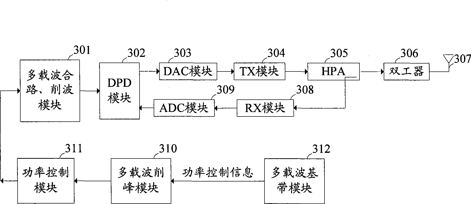
[0032] figure 1 It is a simplified schematic diagram of a multi-carrier downlink structure in which a multi-carrier automatic link control technology is applied in the prior art. 101 in the figure is a multi-carrier combining and clipping module, DPD module 102 is a digital pre-distortion (Digital Pre-Distortion) module, DAC module 103 is a digital-to-analog conversion module, TX module 104 is a transmission module, HPA105 is a power amplifier, 106 is a duplexer, 107 is an antenna, the RX module 108 is a receiving module used as feedback, the ADC module 109 is an analog-to-digital conversion module used as feedback, and the ALC module 110 is an automatic link control (Automatic Link Control, referred to as ALC) module . The existing multi-carrier ALC technology protects the power amplifier by controlling the signal input to the DAC module 103 in the downlink direction.

[0033] Unless otherwise specified, in this application document, the downlink direction refers to the dir...


PUM


Abstract

The embodiment of the invention discloses a multi-carrier peak clipping module which can carry out peak clipping processing to a multi-carrier non-main BCCH carrier according to the input power control information of each carrier of a next time slot so as to obtain the output power of the next time slot of each carrier after the peak clipping and further obtain the new power control information of each carrier of the next time slot. The embodiment of the invention also discloses a multi-carrier control method and a base station. By not carrying out the peak clipping to the main BCCH carrier in a GSM multi-carrier channel, the method for carrying out the peak clipping processing to the non-main BCCH carrier can reduce the total output power of a multi-carrier power amplifier under the condition that the power exceeds ration, thus forming stable GSM network coverage when protecting the reliable operation of a main device so as to guarantee the performance stability of the GSM network.

Description

technical field [0001] The embodiments of the present invention relate to the field of multi-carrier control, in particular to a multi-carrier control method, a multi-carrier peak clipping module and a base station. Background technique [0002] Currently, the GSM multi-carrier power sharing technology is more and more widely used. GSM multi-carrier power sharing technology refers to: In GSM network, not all time slots must be continuously transmitted with full power. For GSM multi-carrier base stations, on the premise that the multi-carrier power The output power is adjusted among multiple carriers to realize over-allocation of carrier power. Carrier power over-allocation means that the sum of the maximum output power of carriers configured in each multi-carrier channel of the multi-carrier power amplifier is greater than the rated output power of the multi-carrier power amplifier. The carrier power over-allocation technology can increase the output power of the time slot...

Claims


Application Information

Patent Timeline
Patent Type & Authority Applications(China)
IPC IPC(8): H04B7/005H04L27/34
CPCH04W52/325H04W52/42H04W52/346H04L27/2623
Inventor 姚国强
Owner HUAWEI TECH CO LTD
Learn More