Eureka AIR delivers breakthrough ideas for toughest innovation challenges, trusted by R&D personnel around the world.

Portable biosensor apparatus with controlled flow

a biosensor and flow control technology, applied in the field of biosensors, can solve the problems of insufficient sensitiveness to detect a variety of analytes, bulky and relatively fragile, and inconvenient field use of biosensors

Inactive Publication Date: 2004-07-27
PRITEST
View PDF51 Cites 74 Cited by
  • Summary
  • Abstract
  • Description
  • Claims
  • Application Information

AI Technical Summary

Problems solved by technology

Presently available biosensors are too bulky and fragile for field use, or are not sensitive enough to detect a variety of analytes from environmental or other field samples.
Typically, these are designed for use in clinical or research laboratories and tend to be very bulky and relatively fragile.
In its commercial form, the biosensor is too bulky and fragile for use under field conditions.
The biosensor is limited to detection of glucose or its close structural analogs and is not suited for detecting a wide variety of analytes.
The use of microchannels with small cross-sectional diameters would result in frequent clogging of the apparatus unless samples are first processed to remove particulate contaminants.
The biosensor is not usable with relatively unprocessed samples that could clog the microchannels.
It is not capable of analyzing multiple samples for the presence of multiple analytes simultaneously.
The manufacturing process is complex, involving the machining of multiple layers before assembly into a fluidics cube.
The use of a patterned reflective coating on the waveguide increases the cost and complexity of manufacture and may be limiting for the types of chemistry used to bind molecules to the waveguide surface.
Non-turbulent fluid flow through the sample channels, the absence of optimized biomolecule attachment sites, and the lack of fixed internal standards result in decreased sensitivity and efficiency of detection.
The use of a bezel and gasket to seal the waveguide to the fluidics cube may result in deformation of channels or damage to the waveguide due to improper tightening.

Method used


Image

  • Portable biosensor apparatus with controlled flow
  • Portable biosensor apparatus with controlled flow
  • Portable biosensor apparatus with controlled flow

Examples


Embodiment Construction

Definitions

As used herein, "a" or "an" may mean one or more than one of an item.

As used herein, the terms "analyte," "target" and "target analyte" mean any compound, molecule or aggregate of interest for detection using the biosensor. Non-limiting examples of analytes include a protein, peptide, carbohydrate, polysaccharide, glycoprotein, lipid, hormone, growth factor, cytokine, receptor, antigen, allergen, antibody, substrate, metabolite, cofactor, inhibitor, drug, pharmaceutical, nutrient, toxin, poison, explosive, pesticide, chemical warfare agent, biowarfare agent, biohazardous agent, infectious agent, prion, radioisotope, vitamin, heterocyclic aromatic compound, carcinogen, mutagen, narcotic, amphetamine, barbiturate, hallucinogen, waste product, contaminant, heavy metal or any other molecule or atom, without limitation as to size. "Analytes" are not limited to single molecules or atoms, but may also comprise complex aggregates, such as a virus, bacterium, Salmonella, Streptoco...


PUM


Abstract

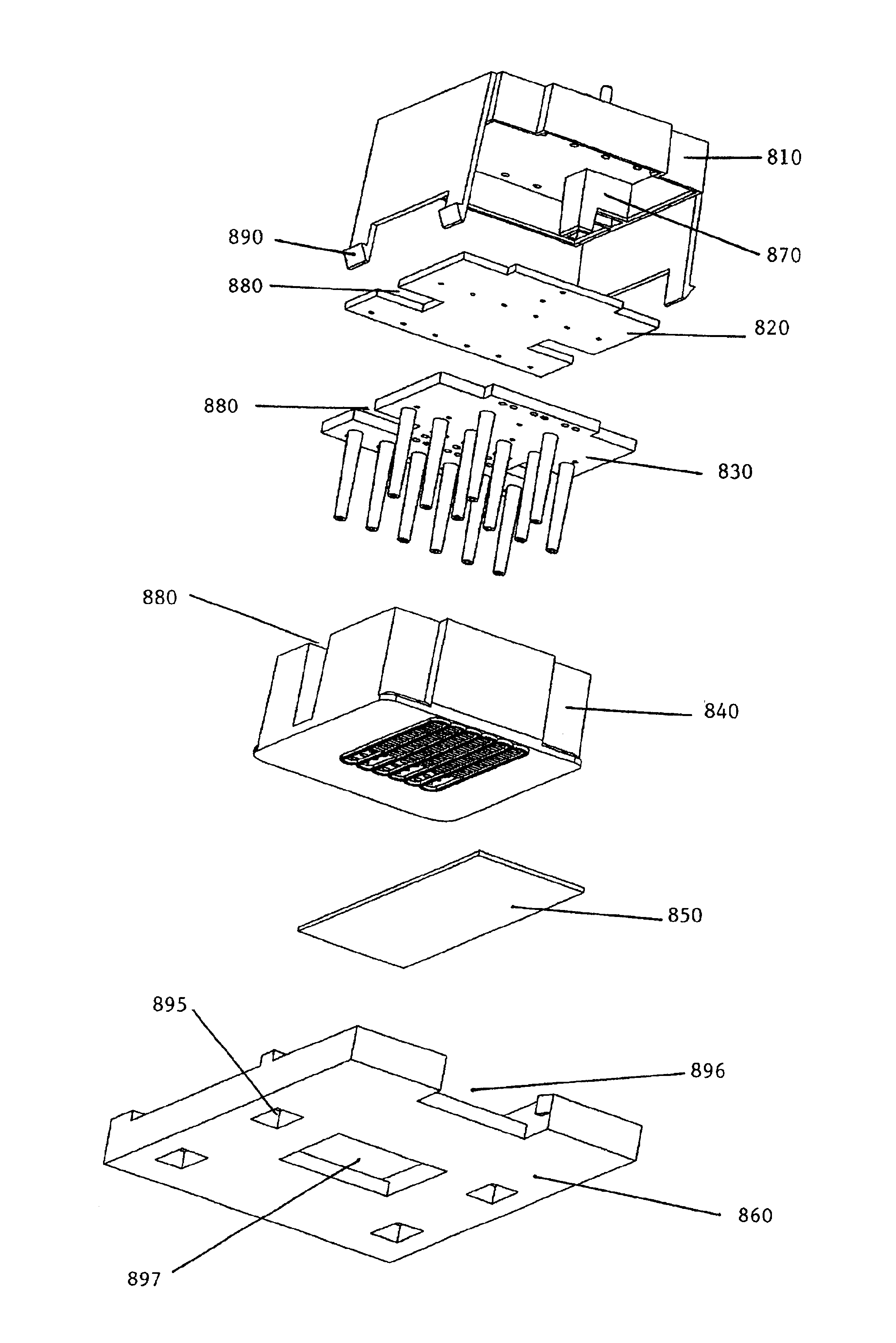
The present invention concerns a portable, reliable and sensitive biosensor apparatus. In certain embodiments, the apparatus incorporates a fluidic cube, comprising a vent cap, vent cap isolator, cube body, waveguide and stage. In preferred embodiments, the fluidic cube further comprises a fluid manifold. In more preferred embodiments, the fluidic cube comprises one or more sample channels that are designed to increase fluid mixing through the use of baffles. The biosensor is designed to simultaneously process multiple samples for a variety of analytes. In certain embodiments, the biosensor is designed to operate as a compact, stand-alone automated unit that can reliably analyze environmental, clinical, veterinary, pathologic or medical samples under adverse field conditions.

Description

1. Field of the InventionThe present invention relates to the field of biosensors. More particularly the present invention relates to methods, compositions and apparatus for a compact, portable, automated biosensor that can detect a wide variety of analytes. Movement of fluids through the biosensor may be controlled to increase the sensitivity and efficiency of analyte detection.2. Description of Related ArtA need exists for a portable, reliable and sensitive biosensor capable of detecting a wide variety of analytes. Preferably, such a biosensor should be simple to use and sturdy enough for field use under a broad range of environmental conditions. Presently available biosensors are too bulky and fragile for field use, or are not sensitive enough to detect a variety of analytes from environmental or other field samples.A biosensor is an apparatus that uses specific and / or selective binding interactions with one or more biomolecules ("ligands"), such as peptides, proteins, enzymes, a...

Claims


Application Information

Patent Timeline
IPC IPC(8): B01L3/00G01N33/543
CPCB01L3/502G01N33/54366B01L3/5027B01L2200/021B01L2200/026B01L2200/16B01L2300/042B01L2300/048B01L2300/0636B01L2300/0654B01L2300/0809B01L2300/0867B01L2400/0487B01L2400/0633
Inventor GREEN, LARRY R.
Owner PRITEST
Why Eureka
Eureka Blog
Learn More