Method and device to measure the brake force for railroad vehicles

a technology for railroad vehicles and brake force, applied in the direction of braking systems, electrical/magnetic measuring arrangements, structural/machine measurement, etc., can solve the problems of non-repeatability of brake force tests, measurement errors, and the largest when compared with errors, so as to improve the consistency of measurements, prevent the surface deterioration of the brake shoe, and improve the accuracy

Inactive Publication Date: 2003-12-16
SCORTEANU ROMEL +1
View PDF1 Cites 10 Cited by
  • Summary
  • Abstract
  • Description
  • Claims
  • Application Information

AI Technical Summary

Benefits of technology

The purpose of the present invention is to provide a new, simpler and more accurate method to measure the brake force for railroad vehicles and which can be used for any type of railcar braking systems. The present invention eliminates the cumbersome task of replacing the actual brake shoe with a specialized measuring shoe. Instead, according to this method, a clearance is opened between the main braking components (brake shoe and wheel tread or brake pads and brake disc), clearance, which is large enough to allow the insertion of a special sensor between these components. The main part of this sensor is a prismatic steel plate with strain gauges bonded on two opposite sides. When the brake is applied, the sensor is compressed between the braking surfaces. Unlike the configuration used by existing brake force testers (single or multiple contact points with the braking surface), the sensor according to the invention comes in contact with the braking surfaces (brake shoe / wheel tread or brake pad / brake disc) through the intermediary of four drill rods. The rods are affixed to the sensor body, two facing the brake shoe and the other two facing the wheel tread. Thus, the mechanical contact between the four rods and the sensor body is over four lines. This configuration virtually eliminates a class of errors related to the non-repeatability of brake force measurements The rods are positioned in such a way (the two on the wheel side near the center of the sensor and the two on the brake shoe side near opposite edges of the sensor) that when the brake is applied the sensor body will be submitted to a bending moment. The signal generated by the strain gauges is processed and displayed on an indicator calibrated in force units. To insure its adaptability to any wheel diameter or wear of the brake components, to improve the consistency of the measurements and to prevent the brake shoe surface deterioration, the sensor uses two steel wings (steel plates of rectangular shape). These wings are elastically seated on the two rods affixed on the brake shoe side of the sensor (for braking systems using a brake shoe) and they are kept in place by rubber membranes. During measurements, the sensor is kept in place by magnets elastically connected to the sensor body.

Problems solved by technology

The measurement errors, the largest when compared with errors from any other known brake force measuring device, are related to the friction in the rigging and to the positioning of the simulated brake shoe.
This device is unstable, hazardous and consequently generates another class of measurement errors.
At this random equilibrium location, the output signal of the measuring system is altered by the effect of bending due to the non-radial position of the compression load cell, leading to non--repeatable brake force test results.
Furthermore, the single point contact unstable condition is magnified when the brake forces are fast applied (for instance in case of an emergency braking), when relatively high braking forces are required and when wider shoe rotations are allowed by the brake specific design.
However, its very complex design (passage ways for the electric wires, retainer being held in place by threaded members, the general design of the cell body with bent endings, an asymmetrical design related to the mechanical attachment of the electrical connector) leads to errors related to the non--linearity and non--repeatability of the measurements.
Also, the friction between the retainer and the shoe head, which cannot be controlled from one test to the next and even during the same test, will generate another class of errors.
These measuring shoes are bulky, heavy, difficult to transport and therefore inconvenient to use.
Furthermore, because the replacement of the actual brake shoe with a measuring shoe alters the friction in the rigging assembly, the measured brake force is prone to errors.
Other shortcomings, mentioned above, were related to the non-linearity, non-repeatability and relatively poor accuracy of the measurements.
As such, it cannot be compared with a brake force-measuring device.
It should be noted, however, that the accuracy of this estimation is poor.

Method used


Image

  • Method and device to measure the brake force for railroad vehicles
  • Method and device to measure the brake force for railroad vehicles
  • Method and device to measure the brake force for railroad vehicles

Examples


Embodiment Construction

As mentioned above, all known methods and devices used to measure the brake force for railway vehicles require the replacement of the brake shoe with a special brake force-measuring shoe (or similarly the replacement of the brake pad with a measuring pad).

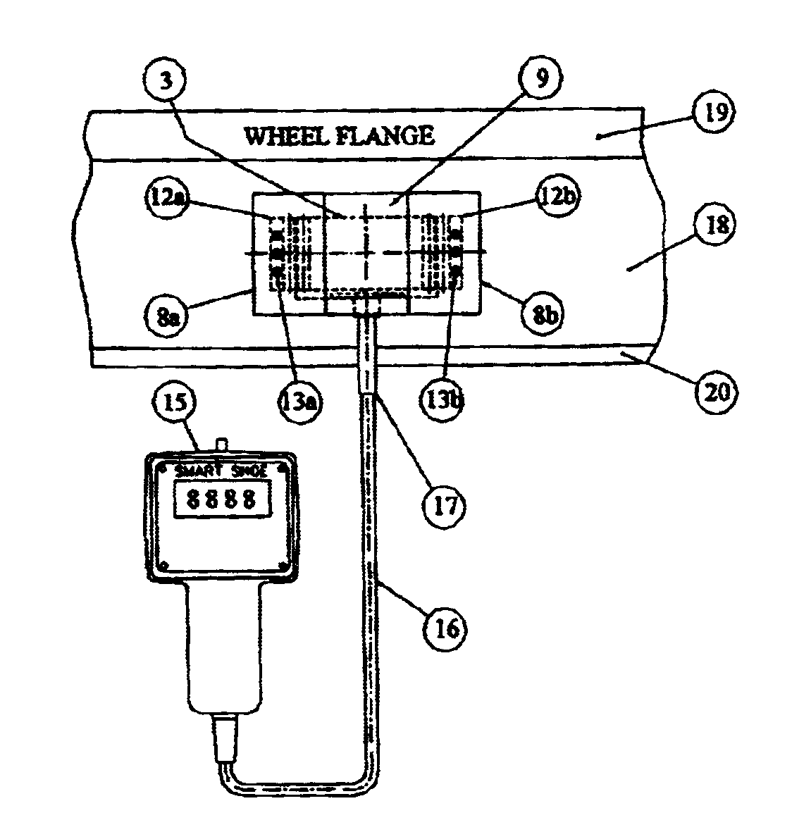
Unlike the known methods and devices, according to the present invention, the brake force is measured directly by inserting a special device (sensor) between the braking surfaces. So, "directly" refers to the fact that currently what is measured is the brake force applied by a measuring shoe, not by the actual brake shoe, with all the shortcomings and limitations mentioned above (this preferred embodiment of the invention refers to the measurement of the brake force for a system using a brake shoe pressed against the wheel tread).

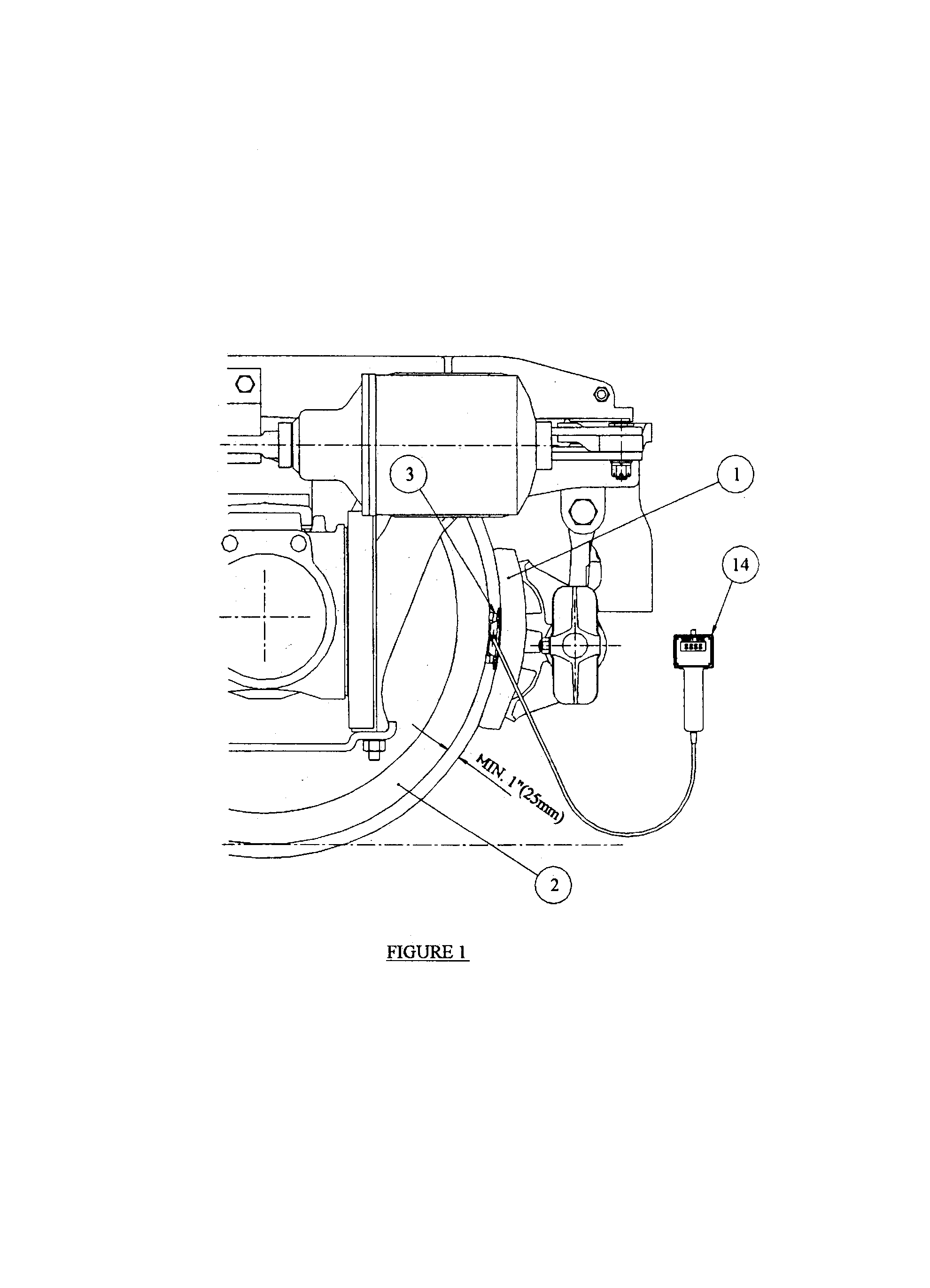
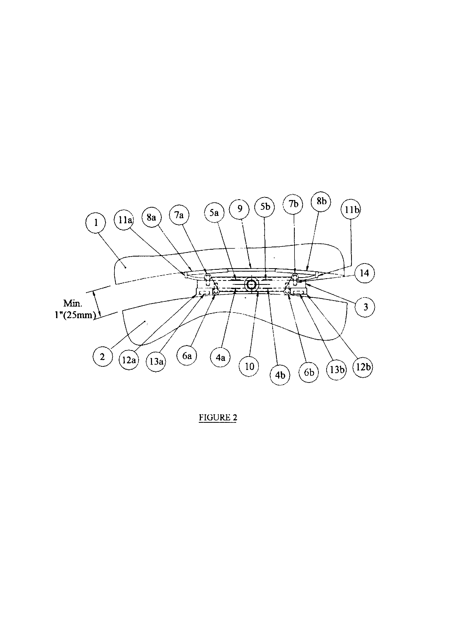
By using a pry bar, a clearance of about one inch can be created between the brake shoe 1 and the wheel tread 2 when the brake is not applied. This will allow the insertion (slide-in) of a special sensor, ...


PUM

PropertyMeasurementUnit
diameteraaaaaaaaaa
brake forceaaaaaaaaaa
bending momentaaaaaaaaaa

Abstract

A method to measure the brake force for railroad vehicles without replacing any part of the braking system, comprising the steps of opening a clearance between the braking elements, inserting a special sensor between the braking elements and applying the brake followed by the processing of the signal generated by the sensor and displaying the result in force units. A device to measure the brake force for railroad vehicles, which uses a sensor, the main part of which is a prismatic steel plate (3) with strain gauges (4a, 4b, 5a, 5b,) on both sides. To measure the brake force, the sensor is positioned, depending on the braking system, between the brake shoe (1) and the wheel tread (2) or between the brake pad and the brake disc. When the brake is applied, the sensor comes in contact with the braking surfaces (brake shoe / brake pad and wheel tread / brake disc) through (the intermediary of) four drill rods (6a, 6b, 7a, 7b,) affixed to the sensor body (3), two on each side, in such a way that the mechanical contact between each rod and the sensor body is over a line and the sensor is submitted to a bending moment. To make the device adaptable to any wheel diameter or wear of the brake components and to protect the brake shoe surface, each of the two rods (7a, 7b,) on the brake shoe side (for braking systems using a brake shoe), has a steel wing (8a, 8b,) elastically seated on it. The wings are kept in place by three rubber membranes (9, 11a, 11b,) connecting the wings between them and to the sensor body. The sensor is kept in place during measurements by two sets of magnets (13a, 13b) embedded into two rubber strips (12a, 12b,) bonded on two opposite sides of the sensor body (3).

Description

BACKGROUND OF INVENTION1. Field of the InventionThe present invention relates to a method to measure the brake force for railroad vehicles and it relates also to a portable device to measure the brake force for railroad vehicles according to the above-mentioned method. More specifically the present invention is related to a method to measure the brake force for railroad vehicles without replacing the brake shoe, brake pad or any other component of the braking system and to display the measured value straight in force units.2. Brief Description of the Prior ArtRailroad vehicles are generally equipped with an air braking system, which typically for freight railcars and locomotives, operates a brake shoe assembly that in turn applies the brake force to the wheel tread. Some passenger coaches use a different braking system the main components of which are a brake disc and brake pads with the pads being pressed against the disc when the brake is applied.Government regulations related to ...

Claims


Application Information

Patent Timeline
Patent Type & Authority Patents(United States)
IPC IPC(8): B60T17/18B60T17/22G01L5/28
CPCB60T17/221G01L5/28F16D2066/005
Inventor SCORTEANU, ROMELPOPISTAS, ALEXANDRU
Owner SCORTEANU ROMEL
Why Eureka
Try Eureka