
Process of manufacturing contact lenses with measured exposure to oxygen

a technology of oxygen exposure and manufacturing process, which is applied in the field of manufacturing contact lenses with measured exposure to oxygen, can solve the problems of significant impact on the manufacturing cost per contact lens, increase yield, etc., and achieve the effect of cost reduction and increased yield

Inactive Publication Date: 2003-08-26
JOHNSON & JOHNSON VISION CARE INC
View PDF28 Cites 11 Cited by
  • Summary
  • Abstract
  • Description
  • Claims
  • Application Information

AI Technical Summary

Benefits of technology

By controlling the time and / or concentration of O.sub.2 in the gaseous mixture to which contact lens mold halves are exposed, the percent of contact lenses having puddle defects has decreased from in some cases over 40% to less than 1%. Contact lenses with puddle defects are discarded in the inspection step during their manufacture. A decrease in the discarded lenses leads to an increased yield, which has a significant impact on the manufacturing costs per contact lens. Additionally, increasing the amount of oxygen present in the enclosed volumes in the production line to the levels specified by this invention will decrease the amount of inert gas, N.sub.2 or other inert gas, which also leads to cost reductions.
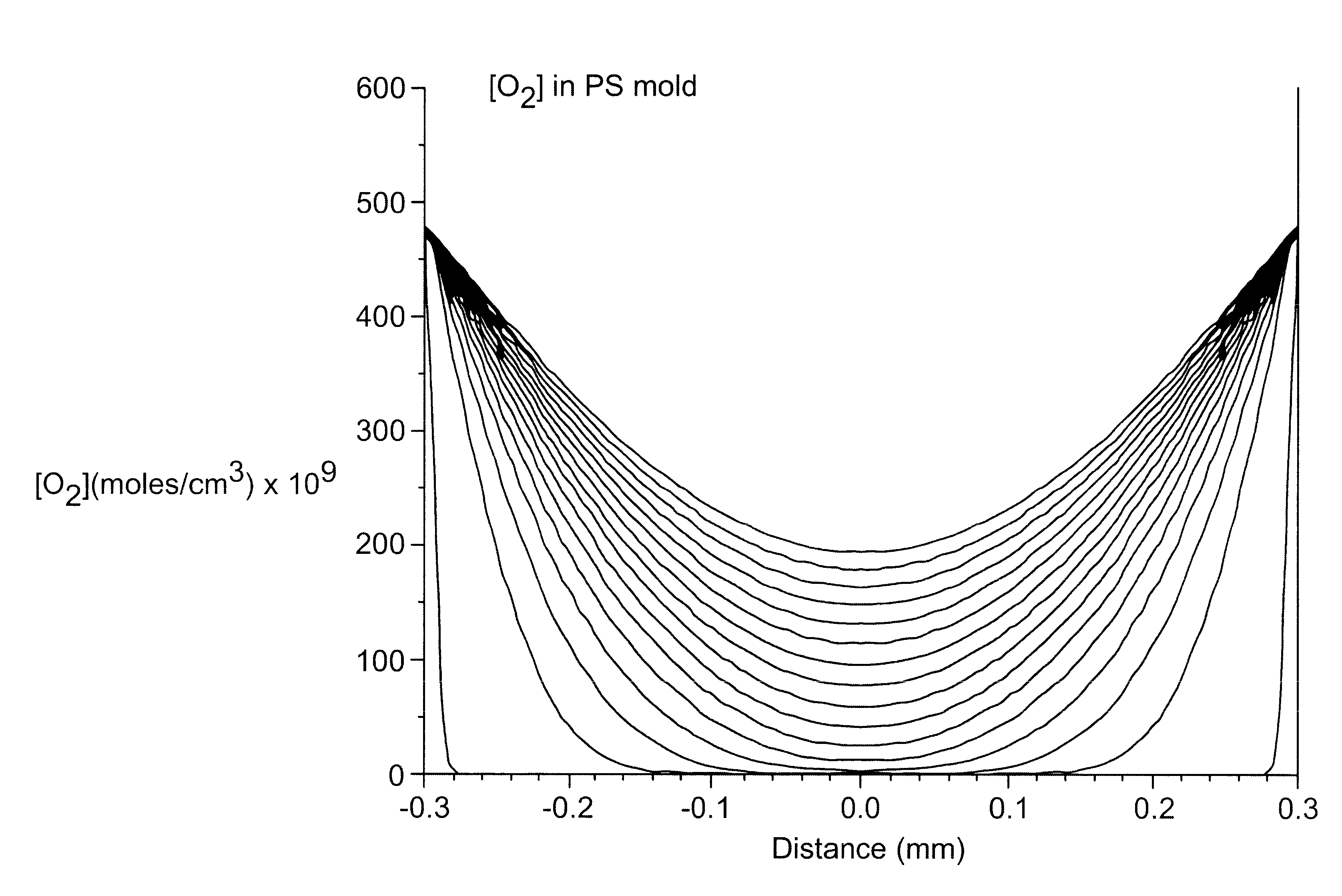
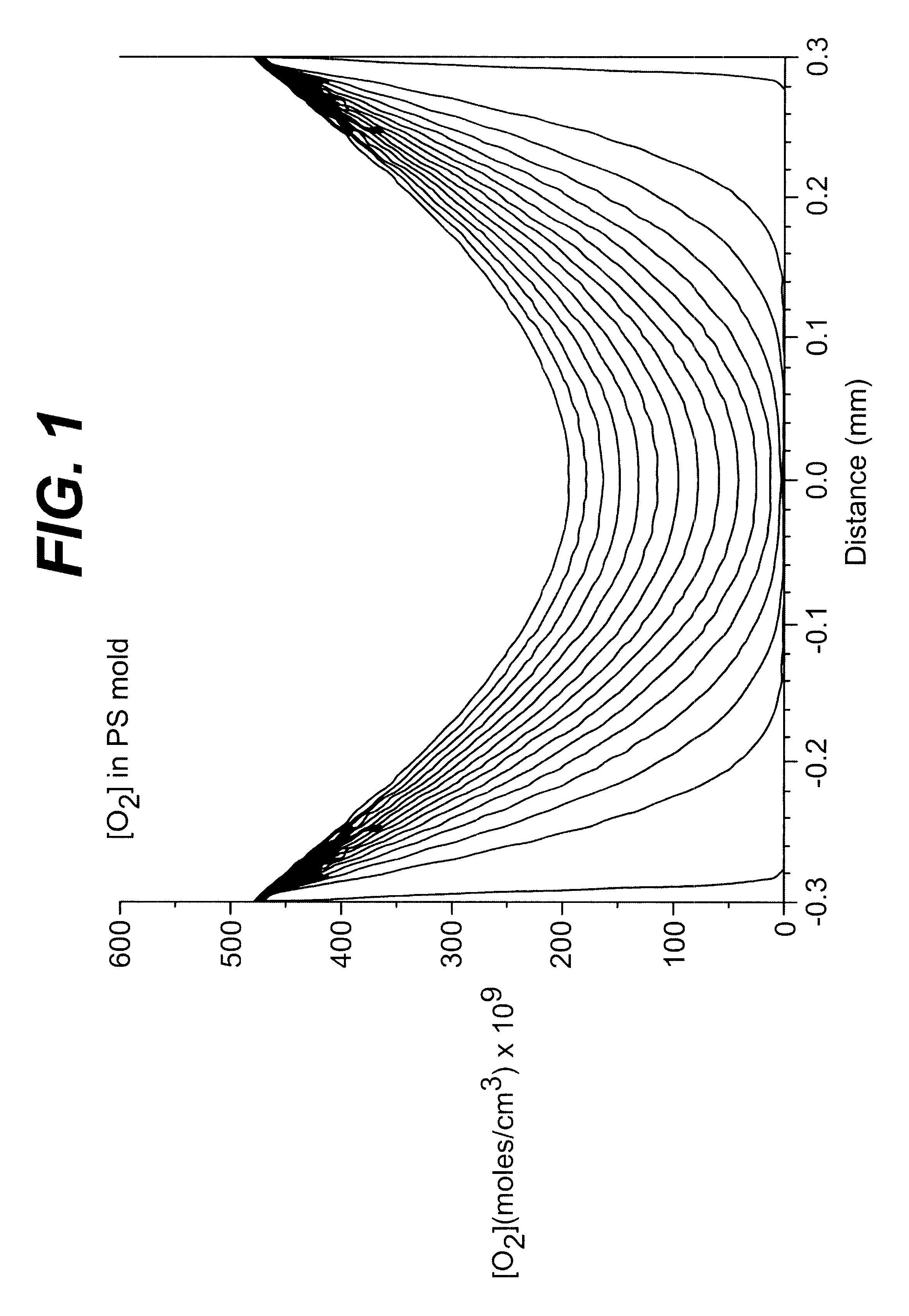
This invention relates to a process for manufacturing polymeric contact lenses in molds. The invention provides that the mold sections or halves are exposed to and / or have absorbed a quantity of oxygen within a specified range or are exposed to a gaseous environment having a specified concentration of O.sub.2. The oxygen in and on the molds benefically interferes with the reaction of the contact lens reaction mixture (reactive monomer, polymerization mixture, or prepolymer mixture) which forms the contact lens in the mold, and thereby decreases the occurance of delamination sites in the contact lens. It is hypothesized that the oxygen slows the reaction so that the material does not quickly shrink away from the optical surfaces of the mold.
It has been discovered that the mold halves dosing and sealing steps, and any transport step or steps to and between the dosing and sealing steps preferably should be carried out in a gaseous environment that allows the optical surfaces of the contact lens mold to absorb more O.sub.2 than had been provided for in the earlier manufacturing processes just prior to closing the mold in the sealing step, but not so much O.sub.2 that the base curve dimensions fall out of specification. That is, there is a range of oxygen present on the optical surfaces of the contact lens mold which provides decreased puddles in the contact lenses manufactured, but does not negatively impact the base curve of the contact lenses.
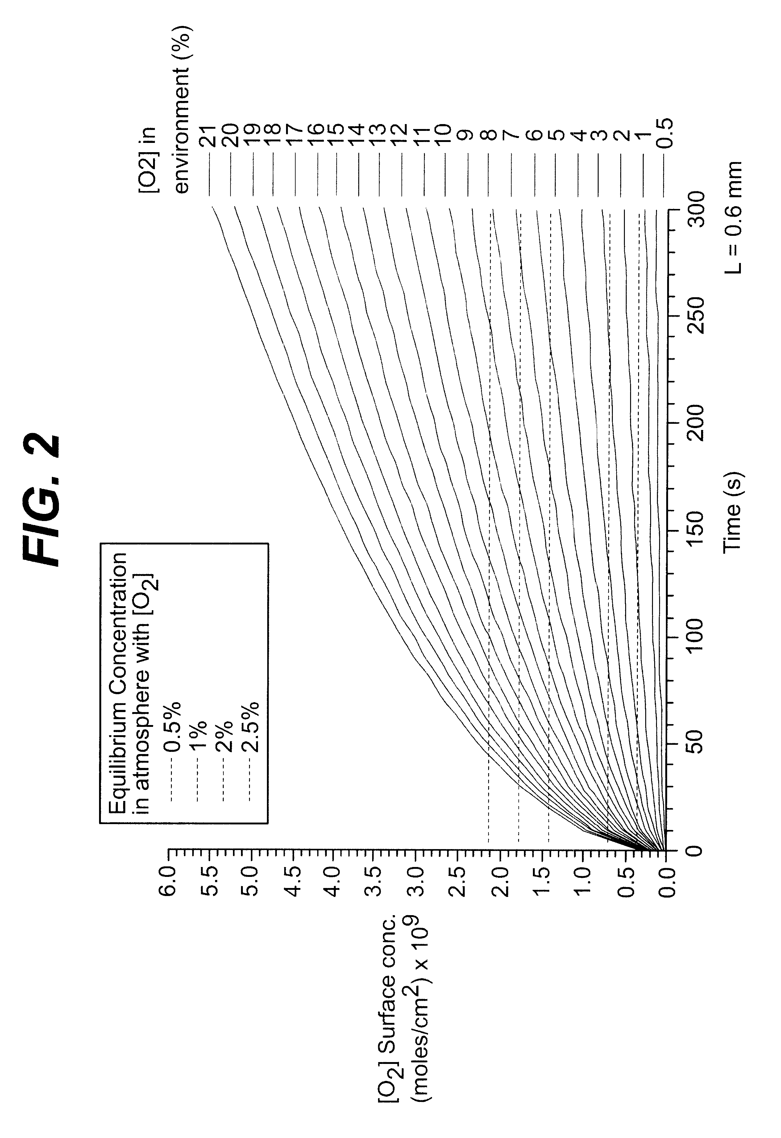
This invention provides a method of manufacturing a contact lens, wherein said optical surfaces of said contact lens mold have between from 0.13.times.10.sup.-9 to 2.6.times.10.sup.-9 moles / cm.sup.2 O.sub.2, more preferably between from 0.17.times.10.sup.-9 to 2.4.times.10.sup.-9 moles / cm.sup.2 O.sub.2, and most preferably between from 0.37.times.10.sup.-9 to 2.1.times.10.sup.-9 moles / cm.sup.2 O.sub.2, available to reduce the reaction rate of the reaction mixture adjacent to the optical surface of said molds.
For any embodiment, if the gaseous environment is 2 to 5 percent oxygen, the exposure time of the optical surfaces of the mold should be between 20 to 1300 seconds, more preferably 30 to 800 seconds. If the gaseous environment is 5 to 10 percent oxygen, the exposure time of the optical surfaces of the mold should be between 40 to 300 seconds, more preferably 60 to 190 seconds. For any embodiment, if the gaseous environment is 0.6 to 4, more preferably 0.6 to 3 and most preferably 0.6 to 2.5 percent oxygen, the exposure time of the optical surfaces of the contact lens mold can be unlimited without having a negative impact on the contact lens parameters.

Problems solved by technology

A decrease in the discarded lenses leads to an increased yield, which has a significant impact on the manufacturing costs per contact lens.

Method used


Image

  • Process of manufacturing contact lenses with measured exposure to oxygen
  • Process of manufacturing contact lenses with measured exposure to oxygen
  • Process of manufacturing contact lenses with measured exposure to oxygen

Examples


Embodiment Construction

Contact lenses comprising Etafilcon A were produced in three types of manufacturing lines, indicated as Manufacturing Lines A, B, and C in the table below.

Manufacturing Line A

Mold sections were prepared by a supplier, packaged and shipped to Vistakon. Prior to their use, essentially all the molecular oxygen was removed from the mold sections by exposing the mold sections to vacuum for a minimum of 8 hours, then the molds were held in a nitrogen environment. Only after the mold sections were inserted into the manufacturing line was oxygen introduced. The levels of oxygen are recorded in the table below.

After the mold sections were inserted into the manufacturing line, they were exposed to the oxygen level listed in the table for the time listed in the table. For all runs, 256 cured mold assemblies were sampled in-process, i.e after exiting the cure tunnel, for puddles and the percentage of lenses with puddles was calculated. In addition, a sample of 50 lenses per run were analyzed fo...


PUM

PropertyMeasurementUnit
depthaaaaaaaaaa
thicknessaaaaaaaaaa
thickaaaaaaaaaa

Abstract

This invention provides a method of manufacturing a contact lens comprising the step of: dosing a contact lens mold comprising optical mold surfaces with an oxygen-sensitive reaction mixture, wherein said optical surfaces of said contact lens mold have between from 0.13x10⁻⁹ to 2.6x10⁻⁹ moles / cm2 O2 available to interfere with the reaction of said reaction mixture. This invention further provides a method of manufacturing a contact lens comprising the steps of: dosing a contact lens mold comprising optical mold surfaces with a reaction mixture, and sealing said reaction mixture and said optical mold surfaces away from a gaseous environment, wherein said optical surfaces of said contact lens mold were exposed to said gaseous environment comprising greater than 0.5 percent oxygen just prior to said sealing step.

Description

This invention relates to the manufacture of polymer contact lenses in an environment that requires the presence of oxygen at the optical surfaces of the contact lens mold in which the contact lens material is reacted.The molding of hydrophilic contact lenses is known. Various processes are disclosed in U.S. Pat. No. 4,495,313, to Larsen; U.S. Pat. No. 4,640,489 to Larsen, et al.; U.S. Pat. No. 4,680,336 to Larsen et al.; U.S. Pat. No. 4,889,664 to Larsen et al.; and U.S. Pat. No. 5,039,459 to Larsen et al., all of which are assigned to the assignee of the present invention.These prior art and other references generally disclose a contact lens production process wherein each lens is molded from a reaction mixture, which can be a reactive monomer or prepolymer mixture. The molding is done by a casting process in which the mixture to be polymerized is deposited into one first mold half or section, often referred to as a front curve, then a second mold half or section, often referred t...

Claims


Application Information

Patent Timeline
Patent Type & Authority Patents(United States)
IPC IPC(8): B29D11/00B29C39/02B29C39/24G02C7/04B29C39/26B29C39/42C08F20/10
CPCB29D11/00125B29D11/0023B29L2011/0041B29L2031/757B29D11/00519Y10S425/808
Inventor CALTRIDER, JEFFREY D.RICARD, JOSEPH W.SPAULDING, TERRY L.STEVEN, JEFFREY E.CALVIN, OLIN W.ENNS, JOHN B.KINDT-LARSEN, TURE
Owner JOHNSON & JOHNSON VISION CARE INC
Learn More