Electrically conductive paste and method of forming circuit

a technology of forming circuit and conductive paste, which is applied in the direction of resistive material coating, non-conductive material with dispersed conductive material, metallic pattern materials, etc., can solve the problems of increasing manufacturing costs, difficult to transmit heat from the heating element, and unavoidable deformation of the insulating substrate 11

Inactive Publication Date: 2003-08-05
YAZAKI CORP
View PDF9 Cites 12 Cited by
  • Summary
  • Abstract
  • Description
  • Claims
  • Application Information

AI Technical Summary

Benefits of technology

In addition, the shape of the complex is not limited, and the aforementioned shapes may be combined in any way, but if at least one of the conductive filler and the heating element is fibrous, whiskery, or dendritic, the complexes in the conductive paste are entangled with each other, so that satisfactory heat transfer is effected. Namely, since the conductive filler is a metal, the conductive filler itself has a high coefficient of thermal conductivity, and satisfactorily transfers heat from the heating element to other entangled complexes, so that the coefficient of thermal conductivity of the conductive paste as a whole becomes higher than the conventional conductive paste, and the unevenness of heat transfer becomes small.
FIG. 2 is a schematic diagram illustrating a cross section of a circuit pattern 4 consisting of the electrically conductive paste of the invention. In this circuit pattern, the complexes each made up by the copper whisker 1 and the iron particles 3, as shown in FIG. 1B, are entangled with each other and are uniformly dispersed in a resin 5. Accordingly, at the time of the formation of the circuit which will be described later, the heat from the iron particles 3 which constitute the heating elements is satisfactorily transferred to the other entangled complexes through the copper whisker 1. Therefore, the thermal conductivity of the conductive paste as a whole is enhanced, with the result that the circuit pattern 4 can be cured without causing the unevenness of curing even with small energy.

Problems solved by technology

In addition, even the insulating substrate 11 formed of a resin other than polyethylene or polypropylene has some expansion or shrinkage due to heating, so that the situation is such that the deformation of the insulating substrate 11 is unavoidable.
However, in the case of the conventional high-frequency induction heating-type conductive paste, since the conductive filler and heating elements (magnetic material) are formed separately, the heating elements between themselves and the heating elements and the conductive filler are separated by the resin, so that the heat from the heating element is difficult to be transmitted.
For this reason, it is necessary to adopt a measure such as making the output of the high-frequency induction coil large or making the heating time longer, so that the manufacturing cost increases.
In addition, in a case where the conductive filler and the heating elements are poorly dispersed in the conductive paste, unevenness of curing occurs in the conductive paste, and the quality of the circuit obtained is low.

Method used


Image

  • Electrically conductive paste and method of forming circuit
  • Electrically conductive paste and method of forming circuit
  • Electrically conductive paste and method of forming circuit

Examples


example 1

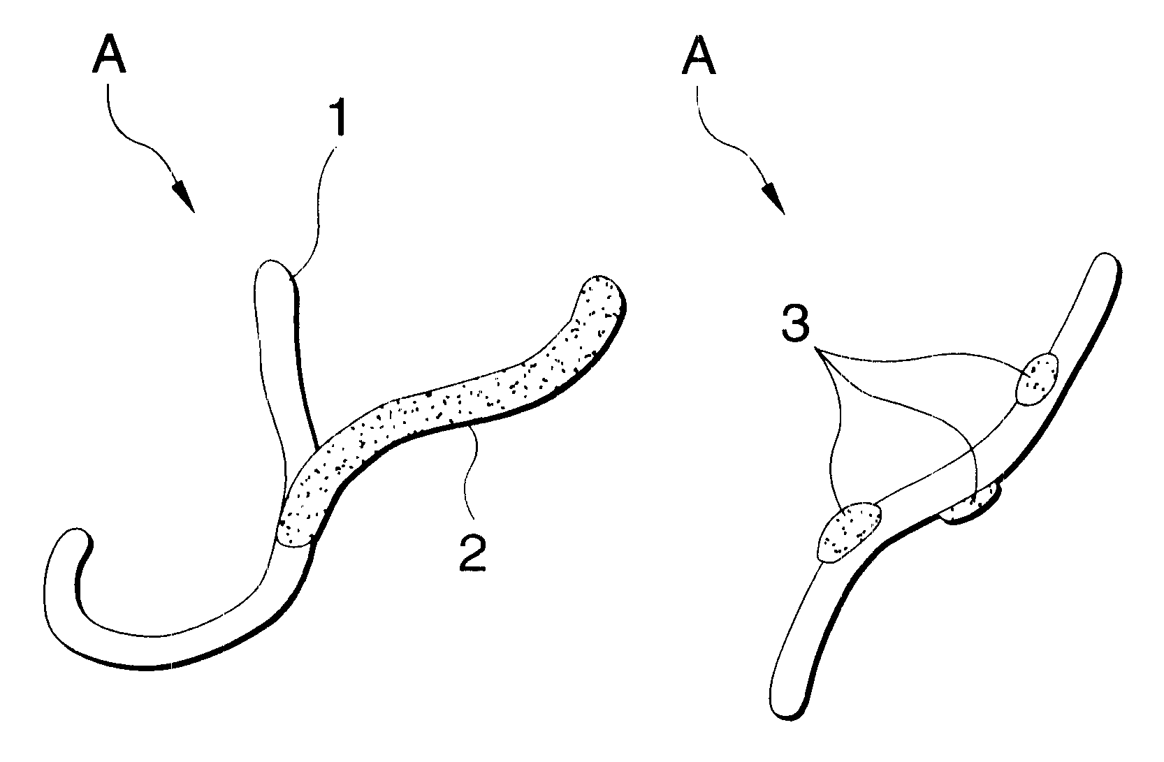
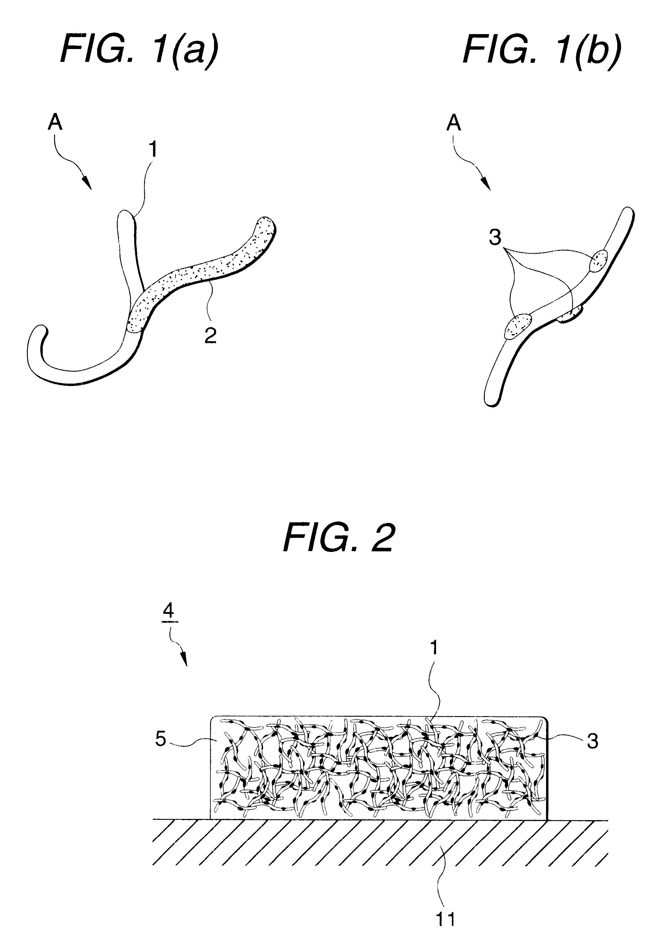
By using a ball mill, 1 mol of copper chloride, 0.1 mol of ferrous chloride, and 1 mol of carbon powder were mixed uniformly, and this mixture was placed in a ceramic boat, was placed in an electric furnace, and was caused to react at 400.degree. C. for 1 hour in an atmosphere of nitrogen gas while introducing steam into it. As a result, it was possible to obtain complexes in which iron particles having diameters ranging from 5 to 10 .mu.m were attached to the surfaces of copper whiskers having lengths ranging from 50 to 80 .mu.m, as shown in FIG. 1B.

Next, these complexes were compounded with a phenolic resin at a ratio of 600 parts by weight of the complexes with respect to 100 parts by weight of the phenolic resin, and were mixed sufficiently, thereby fabricating the conductive paste.

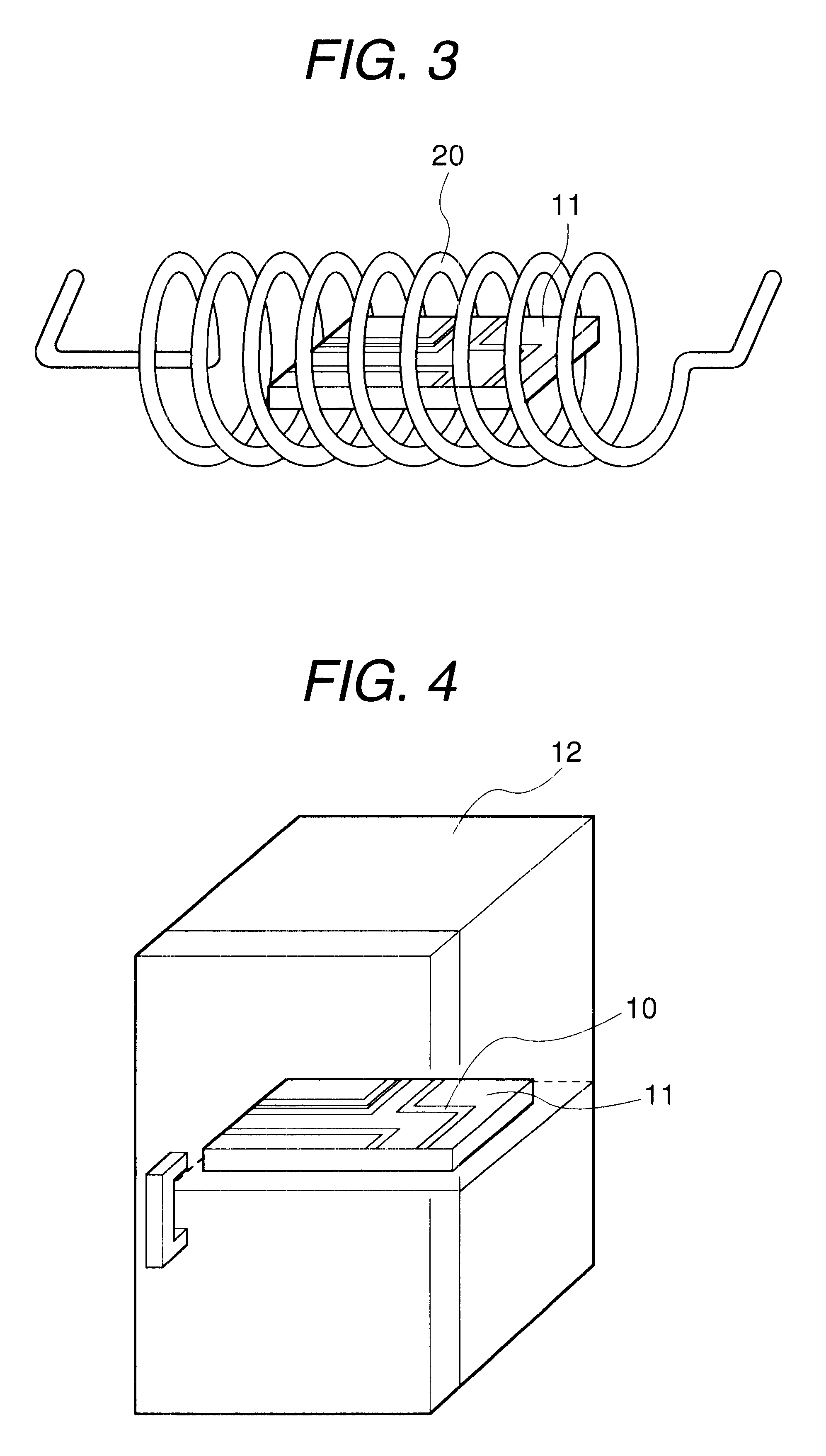
Then, when after a circuit pattern was coated on the insulating substrate made of PET by using the conductive paste obtained, this insulating substrate was disposed in a high-frequency induction coil ...


PUM

PropertyMeasurementUnit
frequencyaaaaaaaaaa
lengthsaaaaaaaaaa
diametersaaaaaaaaaa

Abstract

An electrically conductive paste is provided in that complexes A each made up of an electrically conductive filler 1 and a heating element 3 adapted to generate heat on electromagnetic induction are compounded with a resin 5.

Description

BACKGROUND OF INVENTION1. Field of InventionThe present invention relates to electrically conductive paste used in the manufacture of a printed circuit board or the like and a method of forming a circuit formed by the electrically conductive paste.2. Field of InventionAs a method of manufacturing a printed circuit board, a method is known in which, as shown in FIG. 4, so-called electrically conductive paste 10 in which an electrically conductive filler such as copper, aluminum, and carbon black is dispersed in a thermoplastic resin or a thermosetting resin is coated on an insulating substrate 11 along a predetermined circuit pattern, and this insulating substrate 11 is placed in a heating oven 12 and is heated at a predetermined temperature so as to cure the conductive paste 10.According to this method, it is an essential requirement for the insulating substrate 11 to withstand the curing temperature of the conductive paste 10. For example, in the case of copper phenolic conductive ...

Claims


Application Information

Patent Timeline
Patent Type & Authority Patents(United States)
IPC IPC(8): C08K3/00H01L23/48H01L21/48H01L21/02H01L23/498H05K3/12H05K1/09H05K3/22
CPCC08K3/0075H01L21/4867H01L23/49883H05K1/095H05K3/1283Y10T29/49206H05K2203/1105H01L2924/0002H05K2203/101Y10T29/49155H01L2924/00C08K3/10
Inventor USHIJIMA, HITOSHI
Owner YAZAKI CORP
Why Eureka
Try Eureka