Refrigerator with a plurality of parallel refrigerant passages

a refrigerator and parallel technology, applied in the field of refrigerators, can solve the problems of excessive temperature increase of condenser 15, overloaded compressor 14,

Inactive Publication Date: 2003-07-29
KK TOSHIBA
View PDF9 Cites 35 Cited by
  • Summary
  • Abstract
  • Description
  • Claims
  • Application Information

AI Technical Summary

Benefits of technology

is to provide a refrigerator in which a refrigerating cycle includes two parallel connected passages through which the refrigerant flows into the cold storage zone evaporator and the freezing zone evaporator respectively and in which atmospheres in both the cold storage and freezing compartments can be cooled as quickly as possible without the refrigerating cycle being overloaded and without any other problems so that predetermined temperatures are reached in the cold storage and freezing zones respectively, after power supply to the refrigerator.
Upon power supply to the refrigerator, the refrigerant flows through both the first and second passages. Accordingly, both the cold storage and freezing zones are simultaneously cooled. Furthermore, since rotational speeds of the cold storage and freezing zone fans are adjusted, the refrigerating cycle can be prevented from an overloaded condition and the atmospheres in both zones can be cooled for substantially the same period of time so that the respective set temperatures are reached.

Problems solved by technology

In this case, however, since an amount of refrigerant circulated is increased, there are possibilities that the compressor 14 may be overloaded, that the temperature of the condenser 15 may be increased excessively, that a cooling operation for either one of the cold storage and freezing zones 1 and 2 may be retarded relative to the other to a large extent, and so forth.

Method used


Image

  • Refrigerator with a plurality of parallel refrigerant passages
  • Refrigerator with a plurality of parallel refrigerant passages
  • Refrigerator with a plurality of parallel refrigerant passages

Examples


first embodiment

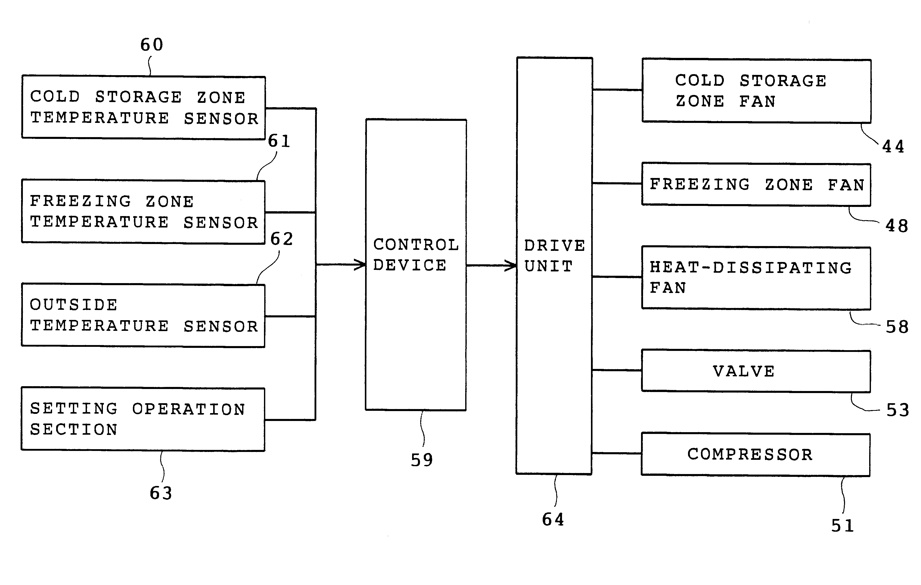
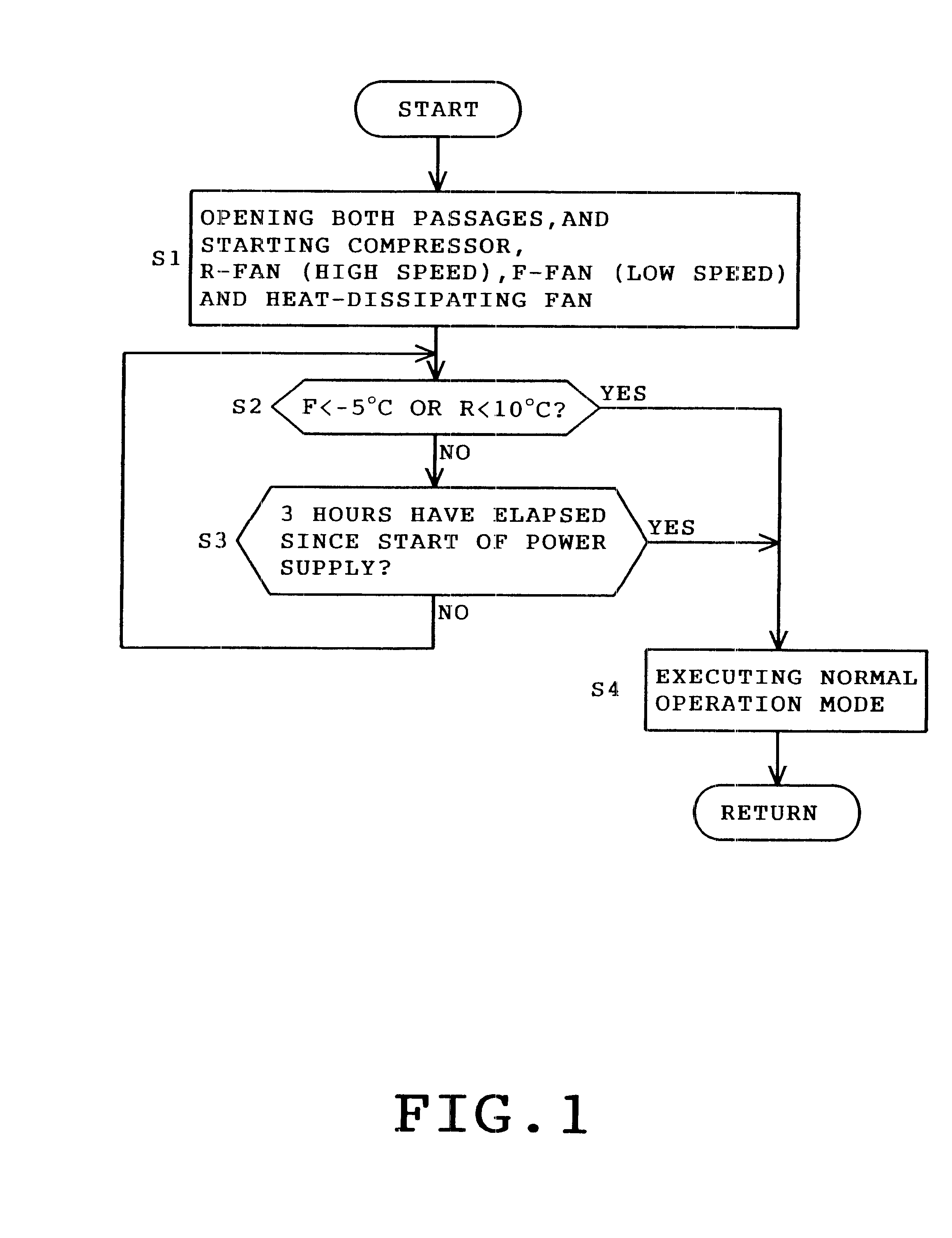
the cooling operation is carried out for both of the cold storage and freezing zones 32 and 33 until the predetermined temperatures are reached in both zones or until the predetermined time elapses after the power supply. Consequently, the temperatures in both zones can quickly be reduced, and the normal operation mode can be initiated a short time after the power supply.

The starting speed of the cold storage zone fan 44 is higher than the starting speed of the freezing zone fan 48 at step S1, as described above. The reason for this is that the temperature in the cold storage zone 32 should be rendered higher than the temperature in the freezing zone 33. Accordingly, the throttling of the cold storage zone capillary tube 54 is lower than the throttling of the freezing zone capillary tube 56 or the opening of the capillary tube 54 is larger than the opening of the capillary tube 56. In other words, the mass flow of refrigerant in the cold storage zone 32 is higher than the mass flow ...

second embodiment

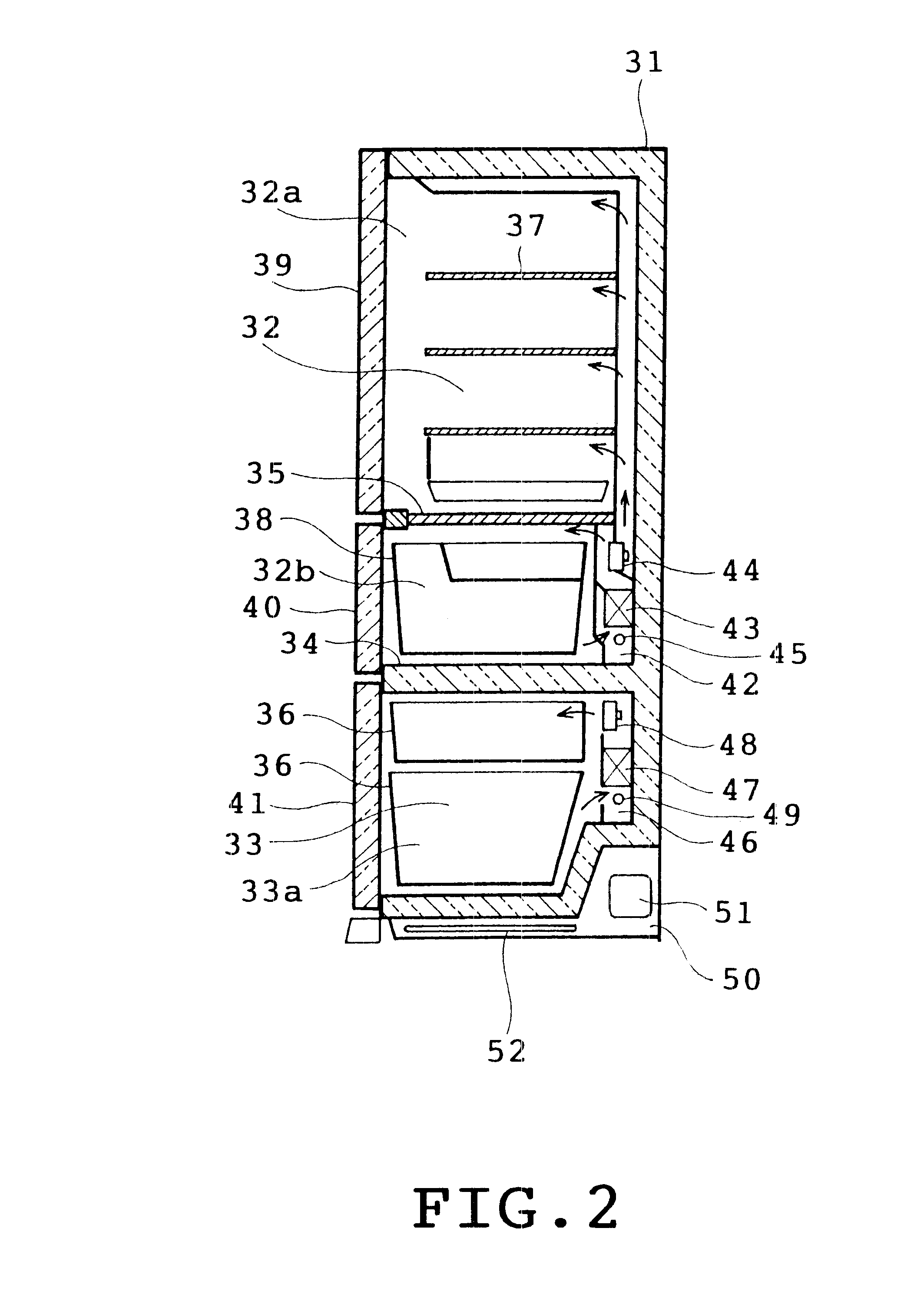
the control device 59 starts cooling the atmospheres in both zones 32 and 33 after a previous cooling operation for the freezing zone 33 where a temperature equal to or lower than the ice point needs to be reached. The refrigerant evaporates in the cold storage evaporator 47 at a temperature lower than in the cold storage evaporator 43. When the refrigerant flows into both zones under the condition where the interior of the refrigerator is not sufficiently cooled, an amount of refrigerant flowing into the evaporator 47 is smaller than into the evaporator 43. Accordingly, the refrigerant evaporates quickly in the evaporator 47 into an overheat gas. On the other hand, a larger amount of refrigerant flows into the cold storage zone evaporator 43. When an overall amount of refrigerant do not evaporate by the heat exchange in the evaporator 47, part of the refrigerant would possibly return to the compressor 51 in the liquid state. When the atmosphere in the freezing zone 32 and the evapo...

third embodiment

In the third embodiment, the compressor 51 is driven with its low compressing performance when the differences between the actual temperatures and the target temperatures in the cold storage and freezing zones respectively are large. The compressor 51 is driven with its low compressing performance when the differences are large, whereas the compressor is driven with its high compressing performance when the differences are small. Thus, the compressing performance of the compressor 51 is reduced when the temperature is high in the refrigerator. Describing the reason for this control manner, the refrigerant evaporated in the evaporators absorbs a sufficient amount of heat in the refrigerator by heat exchange when the temperature is high in the refrigerator, so that the refrigerant returns to the compressor 51 in the phase of a high temperature high pressure gas. When driven at a high speed for compression in this case, the compressor 51 is sometimes overloaded since an amount of refri...


PUM


Abstract

A refrigerator has a cold storage and freezer zones with individual fans and evaporators, a switching valve that allows refrigerant to flow simultaneously through each zone or through only one of the zones and a control which when power is supplied causes simultaneous flow, starting the compressor and a condenser fan while driving the cold storage fan at a high speed and the freezing zone fan at a low speed until such time that a set point time has been exceeded or the temperature set points of the zones has been reached by cooling.

Description

1. Field of the InventionThis invention relates to a refrigerator including a cold storage zone evaporator, a freezing zone evaporator, a first passage through which refrigerant is caused to flow into the cold storage zone evaporator and a second passage through which the refrigerant is caused to flow into the freezing zone evaporator, the first and second passages being in parallel with each other.2. Description of the Related ArtThere have conventionally been provided household refrigerators having a cold storage zone 1 and a freezing zone 2 as shown in FIG. 18. The zones 1 and 2 are divided by a heat insulation partition wall 3. The cold storage zone 1 is further divided by a partition plate 4 into an upper cold storage compartment 1a and a lower vegetable compartment 1b. Only a freezing compartment 2a is defined in the freezing zone 2.A cold storage component compartment 5 is defined deep in the vegetable compartment 1b in the cold storage zone 1. An evaporator 6, a fan 7 and an...

Claims


Application Information

Patent Timeline
Patent Type & Authority Patents(United States)
IPC IPC(8): F25D29/00F25D17/06F25B5/02F25B5/00F25D11/02F25B41/04F25D11/00
CPCF25B5/02F25D17/065F25D29/00F25B41/04F25B2500/26F25B2600/0253F25B2600/111F25B2600/112F25D11/022F25D2317/0682F25D2400/04F25D2400/30F25D2700/12F25D2700/122F25D2700/14Y02B30/741Y02B30/743Y02B30/70F25B41/24F25D11/00
Inventor TEMMYO, MINORUTAGO, MASATO
Owner KK TOSHIBA
Why Eureka
Try Eureka