
Manufacture method of dielectric ceramic composition

a technology of dielectric ceramic and manufacturing method, which is applied in the direction of fixed capacitor dielectric, fixed capacitor details, fixed capacitors, etc., can solve the problems of substantially impossible to produce capacitors with large capacitances, the x7r characteristic of conventional dielectric ceramic compositions is not able to cope with electronic devices with more severe environmental conditions, and achieve excellent high temperature accelerated lifetime characteristics and high permittivity and insulation resistance.

Inactive Publication Date: 2003-04-08
TDK CORPARATION
View PDF36 Cites 46 Cited by
  • Summary
  • Abstract
  • Description
  • Claims
  • Application Information

AI Technical Summary

Benefits of technology

An object of the present invention is to provide a method of enabling to produce a dielectric ceramic composition preferably used as a dielectric ceramic composition for a multilayer chip capacitor wherein base metals like Ni, Ni alloy, etc. can be used for internal electrodes, segregation of different phases other than the main composition is controlled, the fine configuration of the dielectric is controlled, the capacitance-temperature characteristics satisfies the X8R characteristic, dielectric loss is small, permittivity and insulation resistance are high and the high temperature accelerated lifetime characteristic is excellent.
Furthermore, since it is possible to suppress segregation of different phases without changing the composition of additives, a dielectric ceramic composition wherein the capacitance-temperature characteristic satisfying the X8R characteristic can be easily produced.

Problems solved by technology

Recently, the trends are to reduce wire harnesses connecting the electronic device with an apparatus as its object to control and the electronic device is provided outside a vehicle in some cases, so the environment has been getting more severe for the electronic device.
Accordingly, a conventional dielectric ceramic composition having the X7R characteristic is unable to cope with such an application.
Also, as a capacitor material for temperature compensation excelling in the temperature characteristic, (Sr,Ca)(Ti,Zr)O.sub.3 base, Ca(Ti,Zr)O.sub.3 base, Nd.sub.2 O.sub.3 --2TiO.sub.2 base, La.sub.2 O.sub.3 --2TiO.sub.2 base, etc. are generally known, however, since these compositions have a very low specific permittivity (generally, not more than 100), it is substantially impossible to produce a capacitor having a large capacitance.
As a result, there is a problem that inexpensive Ni or other base metals cannot be used as internal electrodes in the capacitor and expensive rare metals like Pd, Au, Ag, etc. have to be used.
While, there arises a problem of deterioration in sintering when alkaline earth is increased in accordance therewith.
Furthermore, Zn has a problem that it is easy to evaporate.

Method used


Image

  • Manufacture method of dielectric ceramic composition
  • Manufacture method of dielectric ceramic composition
  • Manufacture method of dielectric ceramic composition

Examples


example 1

Samples of multilayer ceramic capacitors were produced by the procedure described below.

First, the following pastes were prepared.

Dielectric Layer Paste

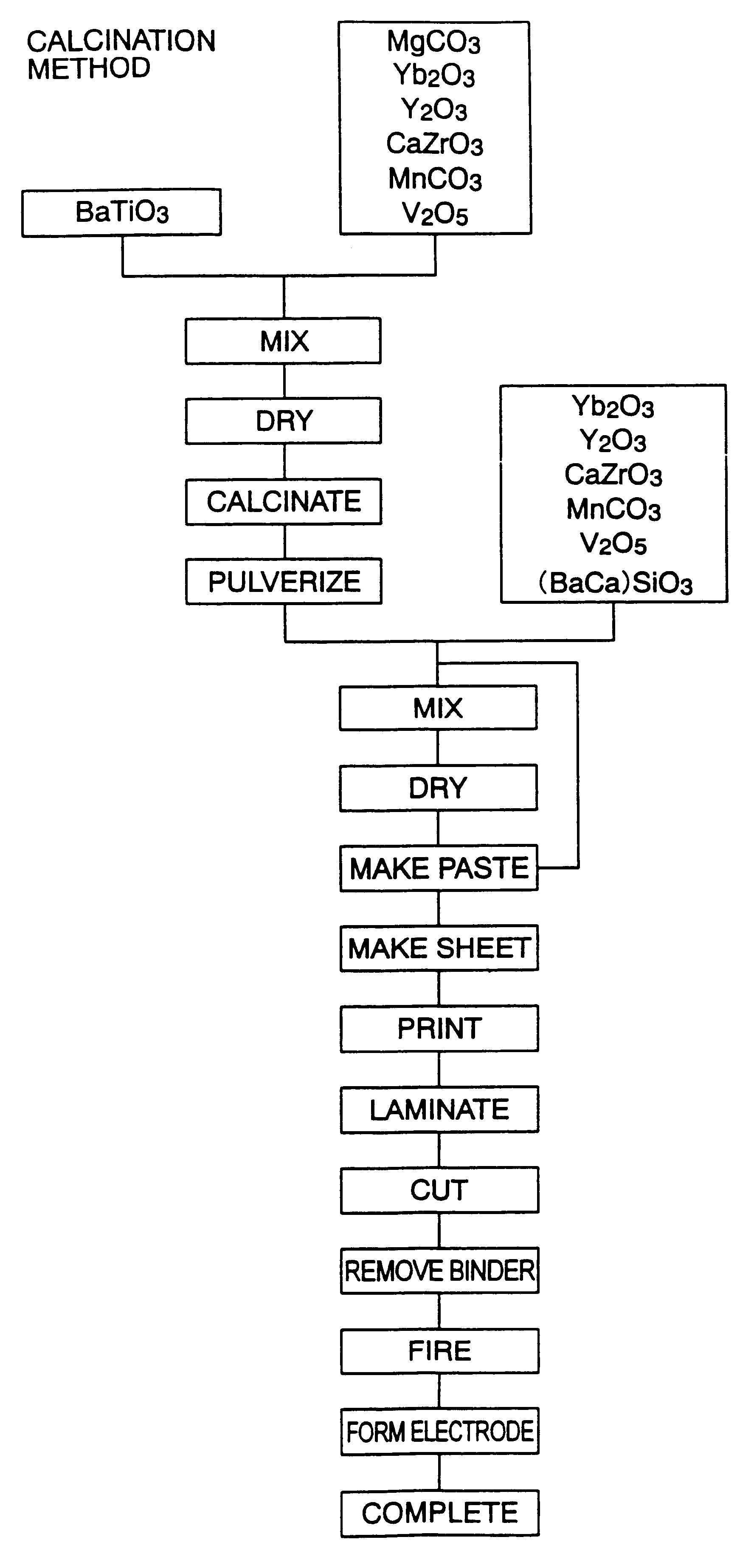
First, ingredients of the main component and ingredients of the subcomponents having a grain diameter of 0.1 to 1 .mu.m were prepared. Carbonates were used for the ingredients of MgO and MnO, and oxides were used for other ingredients. Also, (Ba.sub.0.5 Ca.sub.0.4) SiO.sub.3 was used for an ingredient of a second subcomponent. Note that (Ba.sub.0.5 Ca.sub.0.4) SiO.sub.3 was produced by performing wet mixing by a ball-mill on BaCO.sub.3, CaCO.sub.3 and SiO.sub.2 for 16 hours, drying the result, then firing at 1150.degree. C. in the air and further performing wet pulverlizing by a ball-mill for 100 hours.

At first, pre-calcination powder was prepared by mixing BaTiO.sub.3 as the main component and MgCO.sub.3 as a first subcomponent and drying the result. As shown in Table 1, the pre-calcination powder contained 0.9 mole of MgCO.sub.3 wi...

example 2

Pre-calcination powder was prepared by mixing BaTiO.sub.3 as a main component, MgCO.sub.3 as an ingredient of a first subcomponent and Y.sub.2 O.sub.3 as a fifth subcomponent and drying them. As shown in Table 1, the pre-calcination powder contained 0.9 mole of MgCO.sub.3 and 0.5 mole of Y.sub.2 O.sub.3 with respect to 100 moles of BaTiO.sub.3. When investigating the molar ratio of a specific component (Ba+Mg+Ca+Sr) / (Ti+Yb+Y) in the pre-calcination powder, it was 0.999 as shown in Table 1. The molar ratio of (Ba+Yb+Y) / (Ti+Mg+Ca+Sr) was found to be 1.001 as shown in Table 1.

Next, the pre-calcination powder was calcined to prepare cylinder-shaped samples and samples of capacitors in the same way as in the example 1 except that the calcined powder was added 3.0 moles of (Ba.sub.0.6 Ca.sub.0.4)SiO.sub.3, 0.374 mole of MnCO.sub.3, 0.1 mole of V.sub.2 O.sub.5, 2.1 moles of Yb.sub.2 O.sub.3 and 1.5 moles of Y.sub.2 O.sub.3 as shown in Table 2, and the same tests as in the example 1 were co...

example 3

Pre-calcination powder was prepared by mixing BaTiO.sub.3 as a main component, MgCO.sub.3 as an ingredient of a first subcomponent and Yb.sub.2 O.sub.3 as a fourth subcomponent and drying them. As shown in Table 1, the pre-calcination powder contained 0.9 mole of MgCO.sub.3 and 0.5 mole of Yb.sub.2 O.sub.3 with respect to 100 moles of BaTiO.sub.3. When investigating the molar ratio of a specific component (Ba+Mg+Ca+Sr) / (Ti+Yb+Y) in the pre-calcination powder, it was 0.999 as shown in Table 1. The molar ratio of (Ba+Yb+Y) / (Ti+Mg+Ca+Sr) was found to be 1.001 as shown in Table 1.

Next, the pre-calcination powder was calcined to prepare cylinder-shaped samples and samples of capacitors in the same way as in the example 1 except that the calcined powder was added 3.0 moles of (Ba.sub.0.6 Ca.sub.0.4)SiO.sub.3, 0.374 mole of MnCO.sub.3, 0.1 mole of V.sub.2 O.sub.5, 1.6 moles of Yb.sub.2 O.sub.3 and 2.0 moles of Y.sub.2 O.sub.3 as shown in Table 2, and the same tests as in the example 1 were...


PUM

PropertyMeasurementUnit
Substance countaaaaaaaaaa

Abstract

A method of manufacturing a dielectric ceramic composition comprising at least BaTiO3 as a main component, a second subcomponent having SiO2 as a main component and at least one type selected from MO (note that M is at least one type of element selected from Ba, Ca, Sr and Mg), Li2O and B2O3 and other subcomponents, comprising the steps of mixing in the main component at least part of other subcomponents except for the second subcomponent to prepare a pre-calcination powder, calcining said pre-calcination powder to prepare a calcined powder, and mixing at least said second subcomponent in said calcined powder to obtain a dielectric ceramic composition having ratios of the subcomponents to BaTiO3 as the main component of predetermined molar ratios.

Description

The present invention relates to a method of producing a dielectric ceramic composition having resistance to reduction, a specific permittivity of 1000 or more, a capacitance-temperature characteristic satisfying the X8R characteristic (within -55 to 150.degree. C., within .DELTA.C.+-.15%) of the EIA standard, small dielectric loss, high permittivity, high insulation resistance and an excellent high temperature accelerated lifetime characteristic.A multilayer ceramic capacitor is widely used as a compact, large capacitance, highly reliable electronic device, and the number used in one electronic device reaches large. In recent years, along with devicees becoming compact and high in performance, demands for still more compact, larger capacitance, lower price and more reliable multilayer ceramic capacitor have been getting furthermore stronger.As a dielectric ceramic composition having a high permittivity and a flat capacitance-temperature characteristic, there is known a composition ...

Claims


Application Information

Patent Timeline
IPC IPC(8): C04B35/462C04B35/50C04B35/468H01G4/12
CPCH01G4/1227C04B35/4682C04B35/468
Inventor SATO, SHIGEKITERADA, YOSHIHIROFUJIKAWA, YOSHINORI
Owner TDK CORPARATION
Learn More