
Method and apparatus for tracing hardware states using dynamically reconfigurable test circuits

Inactive Publication Date: 2003-04-01
IBM CORP
View PDF23 Cites 159 Cited by
  • Summary
  • Abstract
  • Description
  • Claims
  • Application Information

AI Technical Summary

Benefits of technology

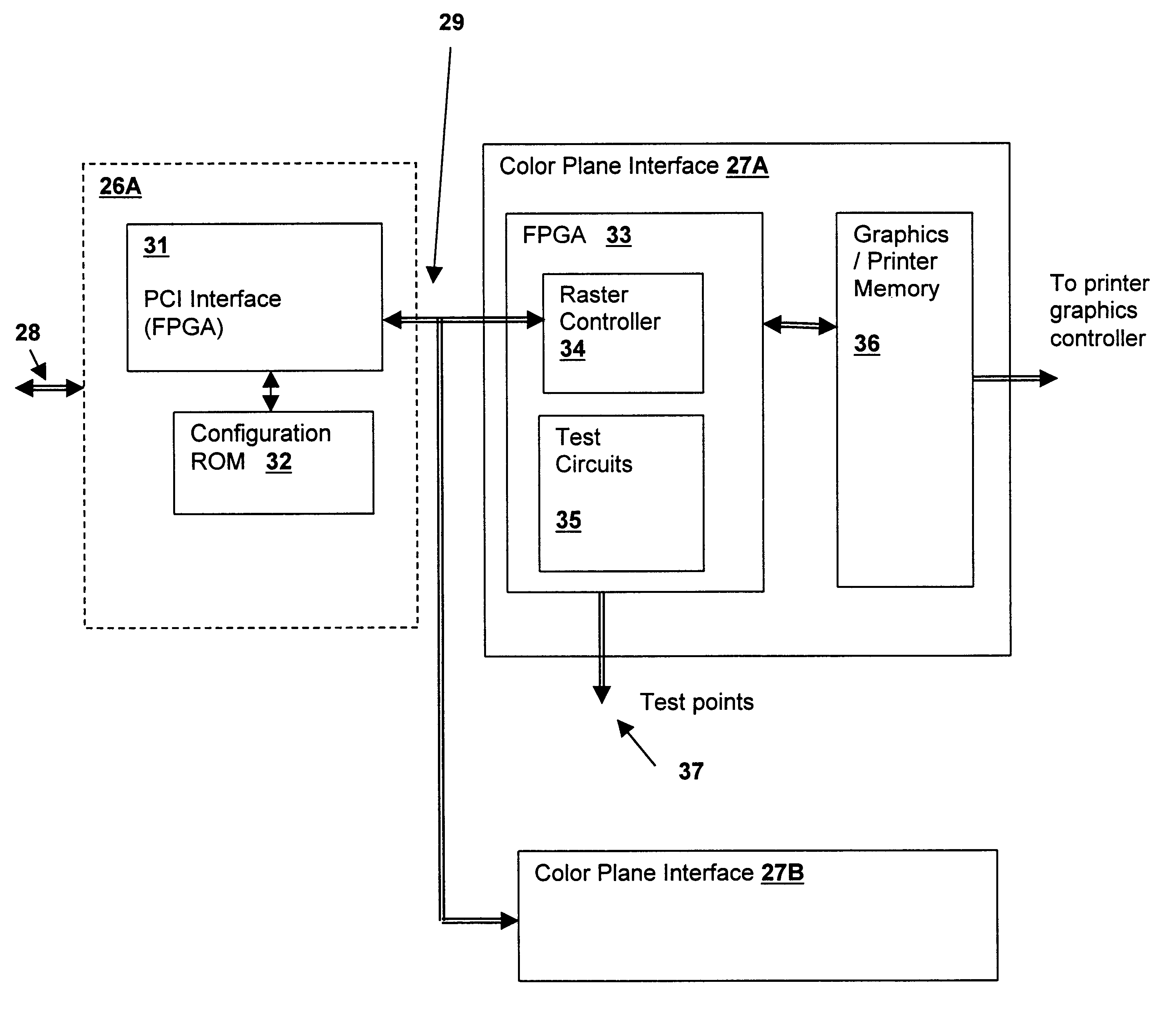
The novel features believed characteristic of the invention are set forth in the appended claims. The invention itself, however, as well as a preferred mode of use, further objectives, and advantages thereof, will best be understood by reference to the following detailed description of an illustrative embodiment when read in conjunction with the accompanying drawings, wherein like reference numerals indicate like components, and:

Problems solved by technology

Because microprocessors and microcontrollers are not efficient for the high-speed serialization / de-serialization of bitstreams, dedicated very-large-scale integrated (VLSI) circuits are used for this purpose.
VLSI circuits have a high non-recurring engineering (NRE) cost for mask design and production tooling.
It would also be desirable to allow for field debugging in cases where there may be a quick solution to a field site problem by modifying the logic, but no ready way to verify the low-level behavior of a new logic design in the field.

Method used


Image

  • Method and apparatus for tracing hardware states using dynamically reconfigurable test circuits
  • Method and apparatus for tracing hardware states using dynamically reconfigurable test circuits
  • Method and apparatus for tracing hardware states using dynamically reconfigurable test circuits

Examples


Embodiment Construction

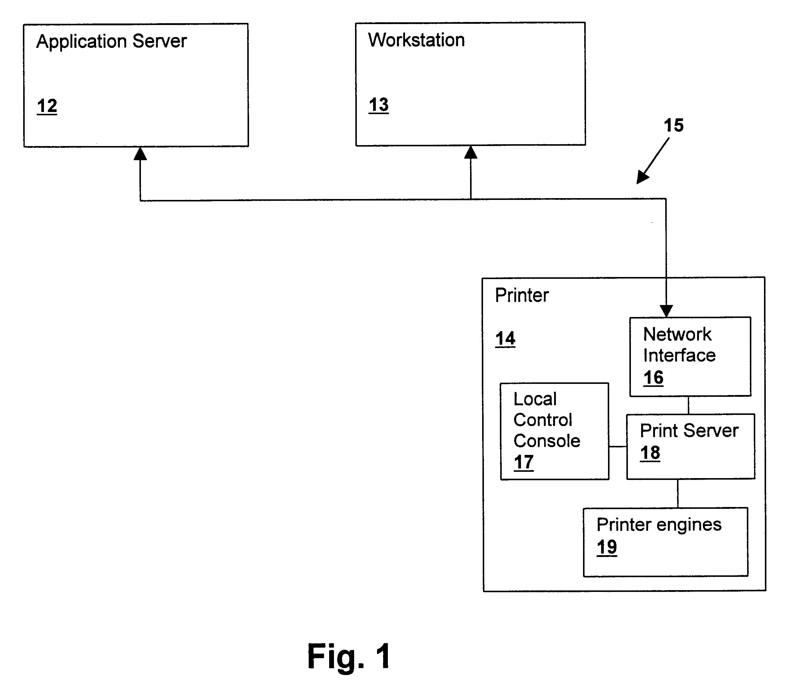
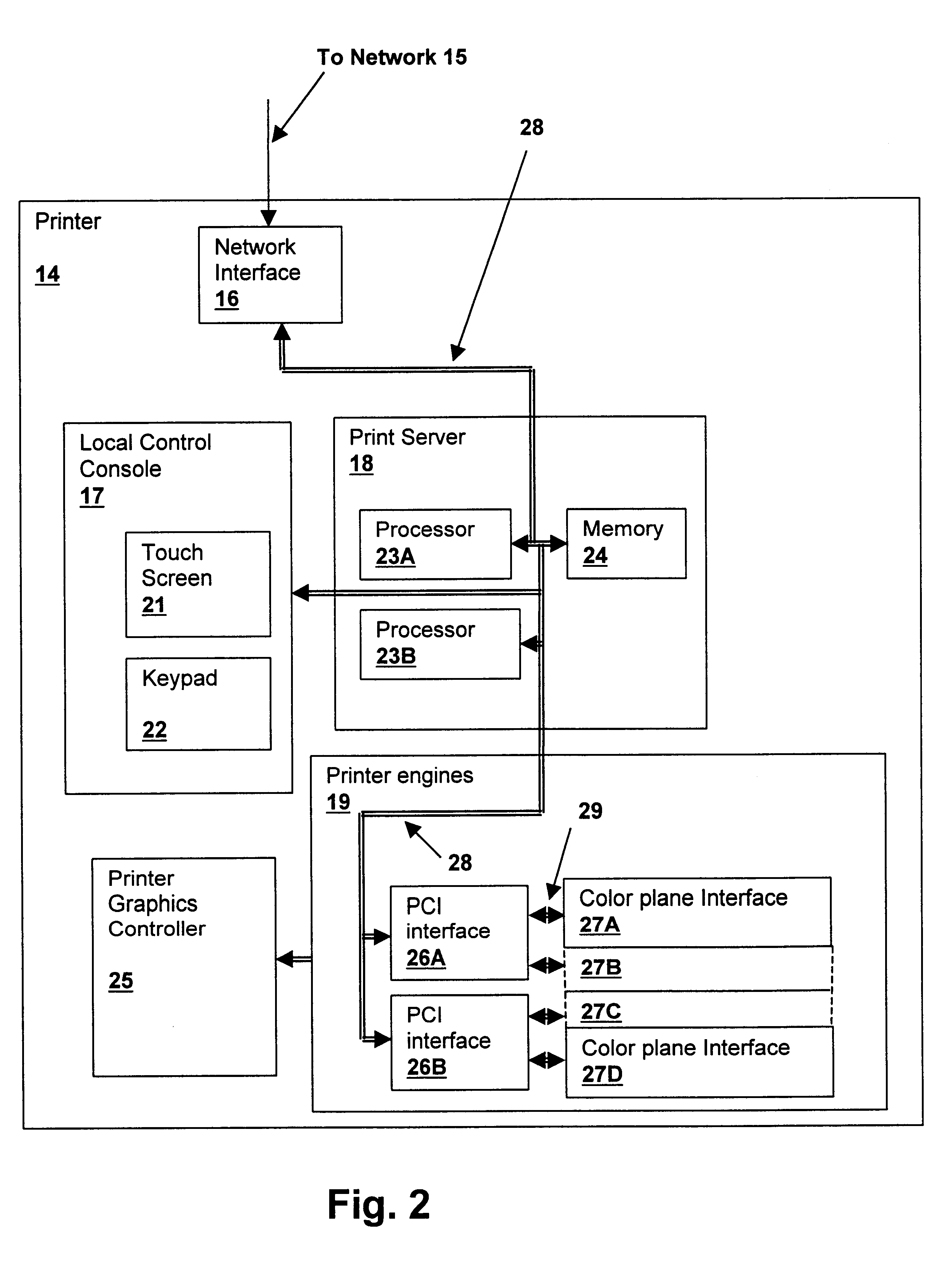
With reference now to the figures, and in particular with reference to FIG. 1, there is depicted a block diagram of a computer network having a network compatible printer, in which a preferred embodiment of the present invention can be implemented. An application server 12 is coupled to a network 15 having a workstation 13 and a printer 14. Application server 12 may perform services requested by workstation 13, such as spooling a print request targeted at printer 14.

Within printer 14, a local control console 17 provides user interface capability for programming and otherwise, controlling operation of printer 14, including selection and display of special test modes in accordance with the present invention. Workstation 13 may also control test modes and trace formats via a network and interface 16 may also be used to display the results of the trace of the present invention. Network interface 16 provides the printer connection to network 15 and receives printer commands and graphics ...


PUM


Abstract

A method and apparatus for tracing hardware states using dynamically reconfigurable test circuits provides improved debug and troubleshooting capability for functional logic implemented within field programmable logic arrays (FPGAs). Special test logic configurations may be loaded to enhance the debugging of a system using FPGAs. Registers are used to capture snapshots of internal signals for access by a trace program and a test multiplexer is used to provide real-time output to test pins for use with external test equipment. By retrieving the hardware snapshot information with a trace program running on a system in which the FPGA is used, software and hardware debugging are coordinated, providing a sophisticated model of overall system behavior. Special test circuits are implemented within the test logic configurations to enable detection of various events and errors. Counters are used to capture count values when system processor execution reaches a hardware trace point or when events occur. Comparators are used to detect specific data or address values and event detectors are used to detect particular logic value combinations that occur within the functional logic.

Description

1. Technical FieldThe present invention relates generally to built-in test circuits implemented in field programmable gate arrays (FPGAs), and more specifically to a method and apparatus for tracing hardware states within an FPGA.2. Description of the Related ArtField Programmable Gate Arrays (FPGAs) provide flexibility in implementing logic designs by allowing reconfiguration of logical circuits via download of binary information. Recent developments in FPGA technology have led to the availability of FPGAs with over 100,000 gates or more within a single Integrated Circuit (IC) package.FPGAs are frequently used in dedicated peripherals attached to computer systems, particularly in graphics applications, where their high speed and reconfigurability yield an advantage. For example, graphics display electronics and printer graphics electronics that convert bit-plane information into serial data streams have been implemented using the FPGA technology. Because microprocessors and microco...

Claims


Application Information

Patent Timeline
IPC IPC(8): G01R31/28G01R31/317G01R31/3185G06F11/25
CPCG01R31/318519G01R31/31713G06F11/25
Inventor HANNA, STEPHEN DALE
Owner IBM CORP
Learn More