
Bottom to surface link system comprising a submarine pipe assembled to at least one float

Inactive Publication Date: 2003-02-25
SAIPEM SA +1
View PDF13 Cites 23 Cited by
  • Summary
  • Abstract
  • Description
  • Claims
  • Application Information

AI Technical Summary

Benefits of technology

The object of the present invention is to provide a novel type of junction between a riser and a can so as to enable large loads to be supported and transferred while mitigating the drawbacks of the above-described floats assembled around said pipe by mutual engagement.
An object of the present invention is thus to provide a novel riser-and-float junction means that is simple, flexible, and reliable, mechanically speaking, and in particular that serves to reduce phenomena of fatigue and wear due to the stresses which act at the junction which is subjected to loads of several hundreds of tonnes.
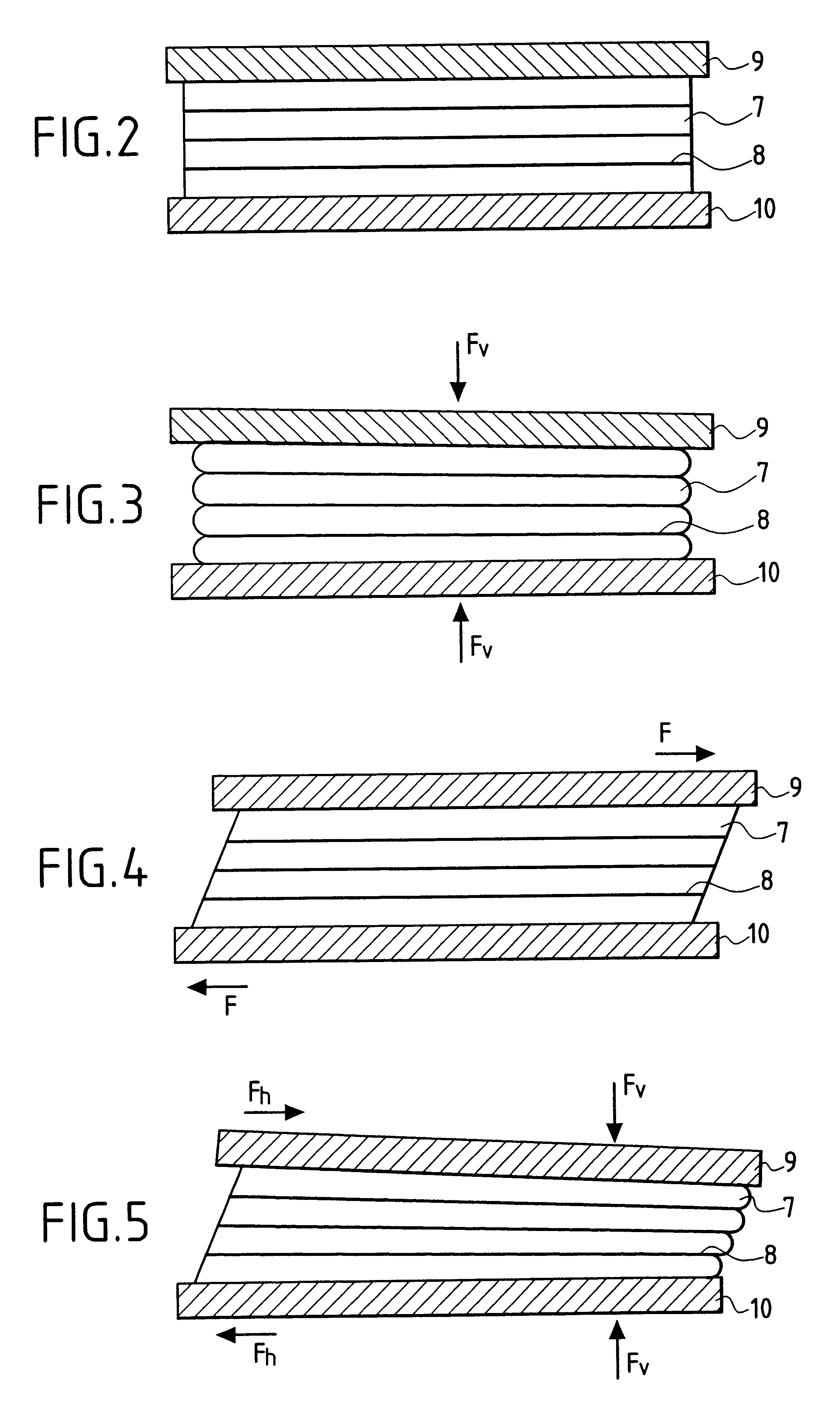
The conical shape in accordance with the present invention contributes to transmitting vertical forces to said pipe in a manner which is progressive. The vertical thrust that acts on the can is transmitted via the laminated abutment in the direction of the axis of said pipe. Said laminated abutment presents much lower stiffness in directions that are perpendicular thereto, said transverse stiffness being adjustable as a function of the quality of the elastomer, the thickness of the various layers of elastomer, and the number of such layers.
The cylindrical shape of the laminated abutment of the invention confers low stiffness to said abutment along the axis of said can and of said pipe, and transmits practically no force in this vertical direction. In contrast, this cylindrical shape presents stiffness in directions perpendicular to thereto which favors the transfer of load between the can and the pipe while also allowing twisting about the transverse axes, and to a smaller extent about the vertical axis.
The combination of a frustoconical plane laminated abutment and a cylindrical laminated abutment favors all twisting and translation movement at the orifices as mentioned above, said twisting movements being associated with said pipe curving within said can.
FIG. 3 is a side view of the same laminated abutment subjected to a compression force F.sub.v, causing its thickness to be reduced;

Problems solved by technology

However this type of foam suffers from the drawback of being very expensive and difficult to make.
This gives rise to considerable lateral and vertical movements (several meters) in the system comprising the riser, the floats, and the barge, particularly in the zone thereof that is subject to swell.
These movements give rise to large differential forces between the riser and the float.
In addition, the curvature taken up by the riser can give rise to very large bending moments in the change of second movement of area that arises where there is a connection between the riser and a float.
Such large variations in second moment of area give rise to poor stress distribution, thus giving rise to highly localized zones where stress can become unacceptable and can lead either to sudden breakage or else to fatigue, leading in turn to the appearance of cracks and then to ruin.
However, it is often necessary to use titanium which is about five to ten times more expensive than the best steels.
Furthermore, these pieces are generally complex in shape and they must be made to extremely high standards in order to guarantee the service expected of them over the lifetime of such equipment which commonly exceeds 25 years.
Such devices can transfer loads corresponding to reducing the weight of a limited length of pipe, but they are not suitable for floats that are intended (on their own and without help from additional tensioning systems secured to the floating support) to support very long lengths of riser, e.g. 500 m to 1000 m, or even more, of the kind to be found in off-shore oil fields at greatdepth, i.e., in particular, at depths of more than 1000 m. The buoyancy required for providing tensioning by means of floats alone requires considerable forces to be transferred vertically and transversely, said vertical forces applied to the head of the riser being capable of reaching several hundreds of tonnes, and in particular lying in the range 300 tonnes to 500 tonnes.

Method used


Image

  • Bottom to surface link system comprising a submarine pipe assembled to at least one float
  • Bottom to surface link system comprising a submarine pipe assembled to at least one float
  • Bottom to surface link system comprising a submarine pipe assembled to at least one float

Examples


Embodiment Construction

In the embodiments of FIGS. 1 to 10, the laminated abutments comprise layers of elastomer and of metal reinforcement between plates having circularly symmetrical surfaces about an axis constituted by the axis ZZ' of said pipe and of said can when at rest.

To clarify the description of the invention, the pipe-and-can assembly is described relative to an orthogonal frame of reference XYZ whose axis ZZ' coincides with the axis of the pipe and the can at rest, whose axis XX' lies in the plane of the figure, and whose axis YY' lies in the plane perpendicular to the Figure.

In FIGS. 1, 6, 7, and 8, the plane laminated abutment is a frustoconical plane laminated abutment comprising a rigid bearing part 9 of frustoconical shape secured via its base to a layer of elastomer 7 in the form of a washer, said frustoconical part having a central cylindrical cavity secured to said pipe, and said elastomer layers 7 and said rigid pieces of reinforcement 8 in the form of superposed washers are inscribe...


PUM


Abstract

A bottom-to-surface link system includes a submarine pipe assembled to at least one float. At least one coaxial can surrounds the pipe. Junctions, which join the can to the pipe at the top and bottom orifices through which the pipe passes, include leakproof joints assembled around the pipe. Furthermore, the leakproof joints are flexible and resilient and are of the laminated abutment type.

Description

1. Field of the InventionThe present invention relates to the known field of bottom-to-surface links of the type comprising a vertical submarine pipe known as a "riser" connecting the sea bed to a floating support located on the surface.2. Description of the Prior ArtOnce the depth of water becomes large, production fields, and in particular oil fields, are generally operated from floating supports. In general, such a floating support has anchor means to keep it in position in spite of the effects of currents, winds, and swell. Such a support generally also has means for storing and processing oil, and means for off-loading oil to off-loading tankers. Such tankers arrive at regular intervals to off-load production. Such floating supports are referred to by the initials FPSO (for floating, production, storage, off-loading). Numerous variants have been developed such as SPARS which are long floating cigar shapes held in position by catenary anchor systems, or indeed TLPs, i.e. tension...

Claims


Application Information

Patent Timeline
IPC IPC(8): E21B17/00E21B17/01F16L1/12F16L1/24
CPCF16L1/24E21B17/012E21B17/01
Inventor DAUPHIN, RAPHAELGASSERT, MICHAELQUINIOU, VALERIEROCHER, XAVIER
Owner SAIPEM SA
Learn More