
Permanent magnets and R-TM-B based permanent magnets

a permanent magnet, permanent magnet technology, applied in the direction of magnetic materials, magnetic bodies, electrical equipment, etc., can solve the problems of high investment cost for production equipment, insufficient information as to the specified means for suppressing the nucleation of demagnetizing field to improve coercivity, and difficult to achieve drastic improvement of magnetic properties

Inactive Publication Date: 2003-01-28
HITACHI METALS LTD
View PDF9 Cites 28 Cited by
  • Summary
  • Abstract
  • Description
  • Claims
  • Application Information

AI Technical Summary

Benefits of technology

The present invention provides a guideline for designing permanent magnets having high magnetic performance, in particular coercivity. Up to now, the structure of the interface between the major phase and the grain boundary phase responsible for coercivity was not known. Since the ideal interface structure for improving the coercivity has been clarified by the present invention, a new guideline for developing permanent magnets is provided, while the pre-existing permanent magnet (particularly, R--TM--B based one) can be improved further in coercivity. The result is that novel permanent magnet materials can be found easily, while permanent magnet (particularly, R--TM--B based one), so far not used practically because of the low coercivity, can be put to practical use, and an optimum composition can be determined easily.
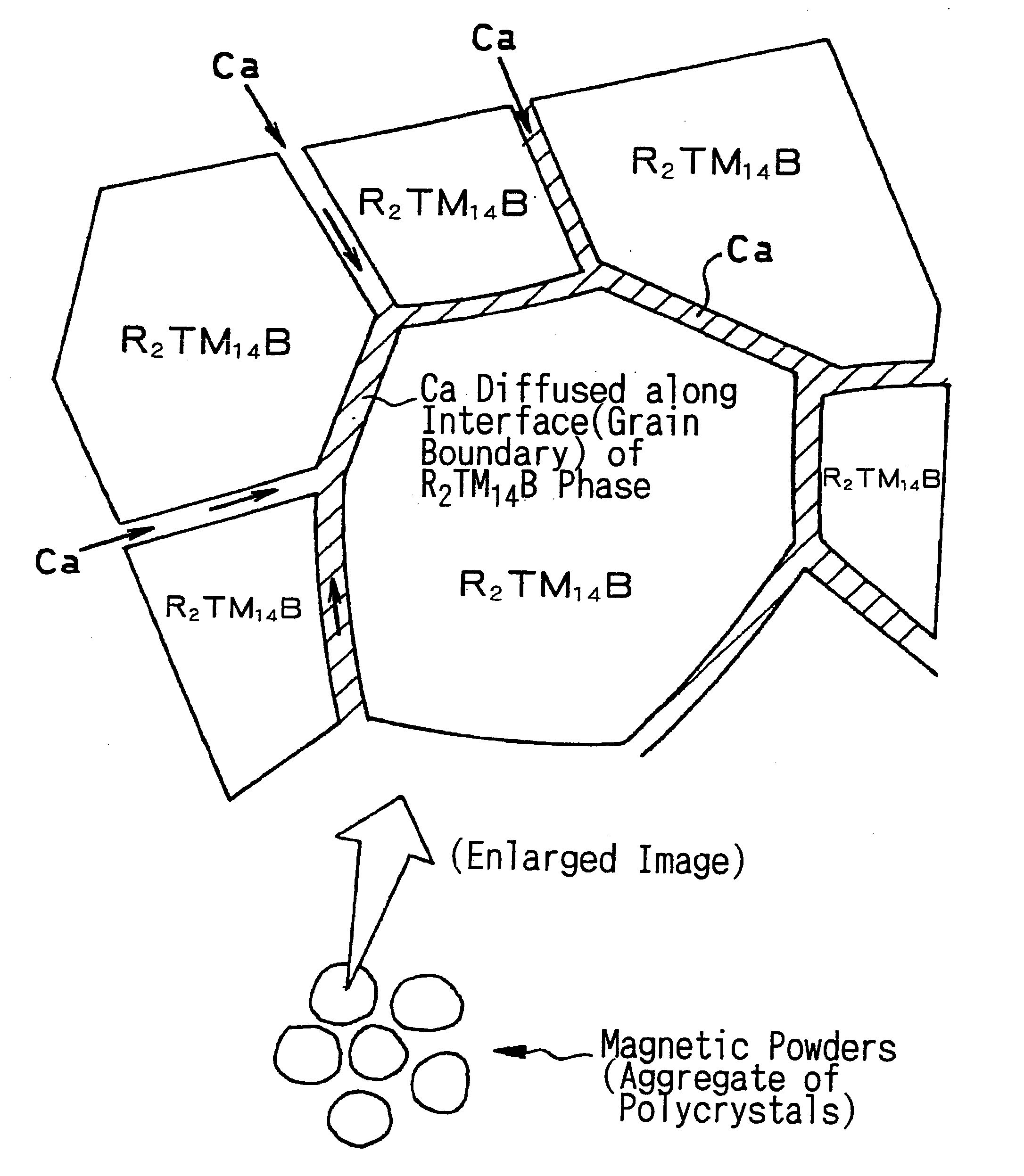
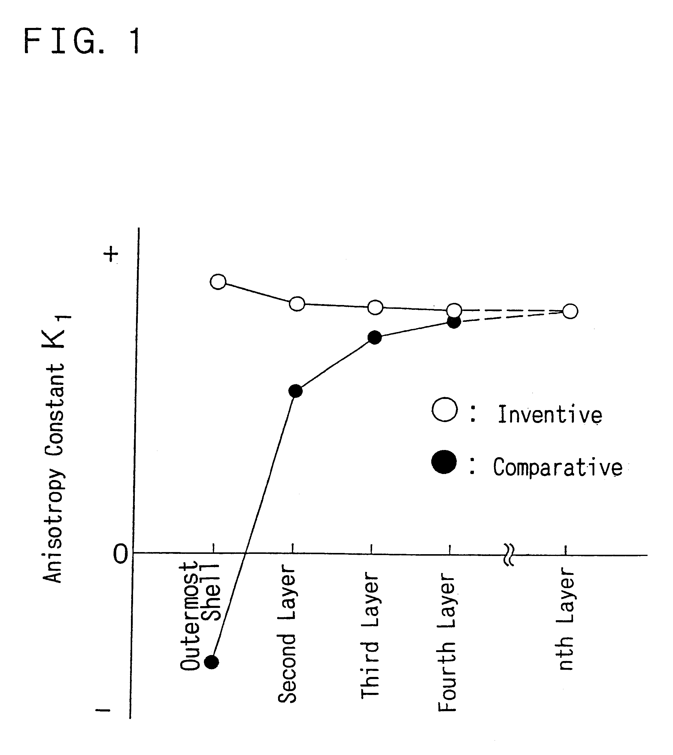
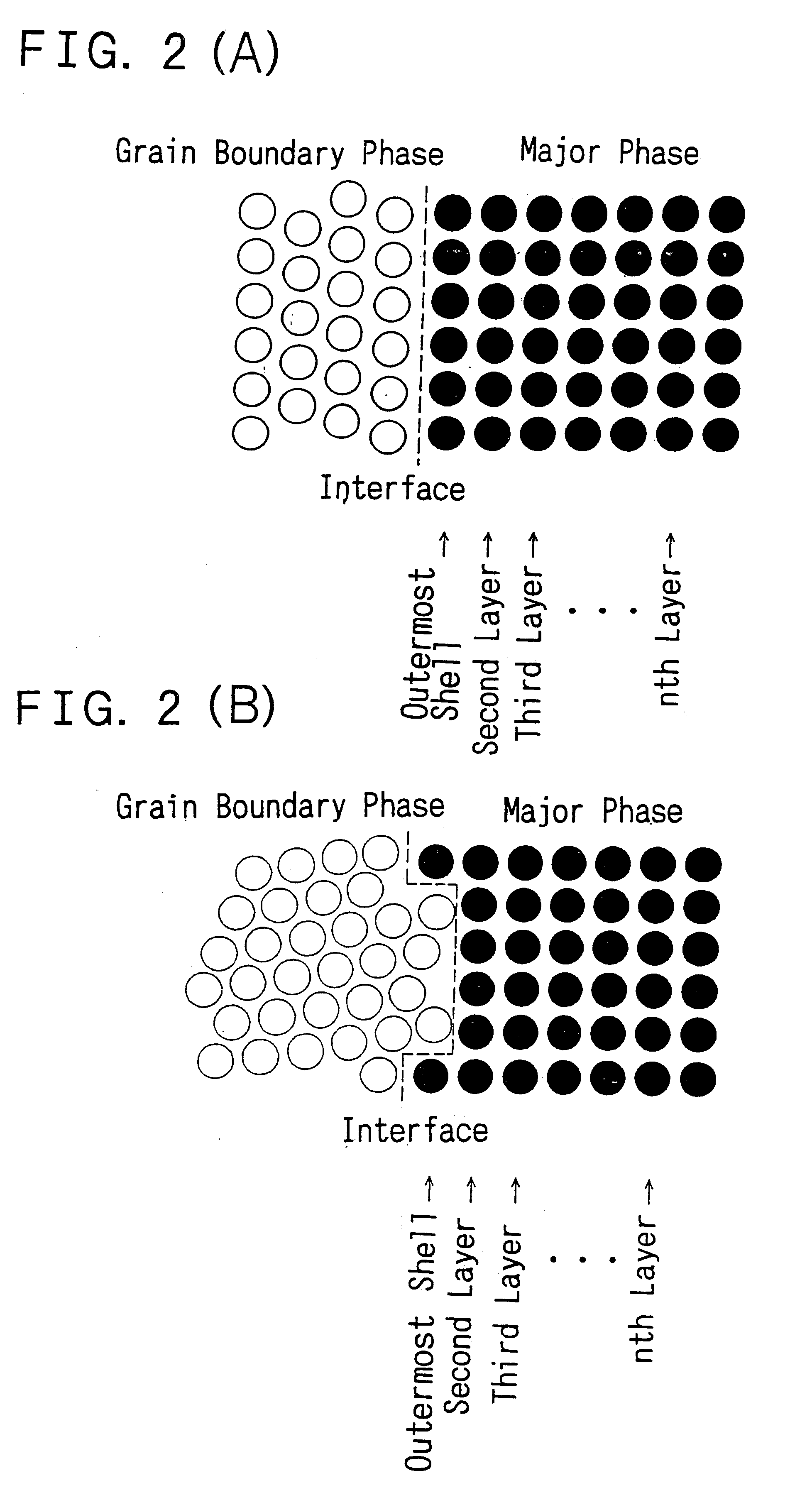
With the R--TM--B based permanent magnet according to the present invention, the relative position between atoms in the interface between the major and grain boundary phases is regular and matched with each other, thereby decreasing the possibility of the interface operating as an originating point of the inverse magnetic domain (demagnetizing field) to achieve high coercivity. Also, the R--TM--B based permanent magnet according to the present invention has superior magnetic properties since specified crystal orientation between the ferromagnetic phase and the grain boundary phase strengthens the crystal field of the R atom in the major phase in the vicinity of the interface to raise the magnetocrystalline anisotropy in the vicinity of the interface of the major phase so that the inverse magnetic domain in the vicinity of the grain boundary can hardly be produced to render facilitated inversion of magnetization difficult.
The magnetic powders of the rare earth element for bonded magnets, obtained with the present invention, are superior in magnetic properties as compared to those obtained with the conventional rapid solidification method or HDDR method and can be manufactured by a simpler method. Therefore, by applying the powders of the present invention, the rare earth element bonded magnets can be produced at a lower cost to provide inexpensive rare earth element bonded magnets with high magnetic properties. The inventive powders are particularly useful as the magnetic powders for high coercivity materials. In the midst of a demand for magnet size reduction, the present invention provides a technique useful for improving coercivity of the ultra-small-sized Nd.sub.2 TM.sub.14 B based magnet.

Problems solved by technology

That is, while it has been predicted that, in the conventional techniques, the coercivity of the nucleation type magnet is governed by nucleation of the demagnetizing field, sufficient information has not been acquired as to specified means for suppressing nucleation of the demagnetizing field to improve the coercivity.
However, with such an empirical method, it is difficult to achieve drastically improved magnetic properties.
In the above-described a manufacturing method in which the Nd.sub.2 Fe.sub.14 B crystal grain size in the powdered particles is less than the single magnetic domain particle size, the rapid solidification method and the HDDR method suffer from the defect that the investment costs for production equipment are high and the manufacturing conditions are severe to raise the cost.

Method used


Image

  • Permanent magnets and R-TM-B based permanent magnets
  • Permanent magnets and R-TM-B based permanent magnets
  • Permanent magnets and R-TM-B based permanent magnets

Examples


example 1

Nd.sub.2 Fe.sub.14 B crystal grains, with a grain size of 10 .mu.m, were press-consolidated under orientation in a magnetic field. 5 wt % of Ca metal powders, pulverized to not more than 200 .mu.m, were sprinkled over the surface of the green compact, heated in vacuum at 800.degree. C. for one hour and cooled. The resulting sample was of such a structure in which crystal grains of Nd.sub.2 Fe.sub.14 B as the major phase are surrounded by the grain boundary phase of Ca metal, with the two phases being directly contacted with each other with a epitaxial interface in-between. The sample has a coercivity of 1.3 MA / m.

example 2

On the surface of Sm.sub.2 Fe.sub.17 N.sub.x, where x is approximately 3, having a grain diameter of 10 .mu.m, Zn was coated in an amount of 2 wt % by an electroless plating method. The resulting mass was heated in vacuum at 450.degree. C. for one hour and cooled. The resulting sample was of a structure in which Sm.sub.2 Fe.sub.17 Nx crystal grains as the major phase were surrounded by a Zn metal phase, with the two phases being directly contacted with each other with an epitaxial interface. The sample had a coercivity of 1.9 MA / m.

example 3

On the surface of a thin SmCo.sub.5 film of 80 .mu.m thick, prepared by the sputtering method, as a substrate was heated to 700.degree. C., Y was coated to a thickness of 5 .mu.m by the sputtering method, as the substrate was heated to 400.degree. C. By X-ray diffraction, the crystal structure of SmCo.sub.5 in the sample film obtained had a hexagonal CaCu.sub.5 structure, while Y had a La type structure of the hexagonal close-packed structure, with the two having a crystal azimuth such that its c-axis is perpendicular to the film surface. Observation of the structure of the sample cross-section over a transmission electronic microscope revealed that the SmCo.sub.5 phase was formed in a columnar crystal state of several .mu.m in diameter, with an epitaxial interface between the SmCo.sub.5 phase and the Y phase. The thin film had a coercivity of 1.5 MA / m.


PUM

PropertyMeasurementUnit
angle of orientation deviationaaaaaaaaaa
angleaaaaaaaaaa
particle sizeaaaaaaaaaa

Abstract

Permanent magnets in which the ferromagnetic phase is matched with the grain boundary phase, and permanent magnets in which magnetocrystalline anisotropy in the vicinity of the outermost shell of the major phase is equivalent in intensity to that in the inside to suppress nucleation of the inverse magnetic domain. Guideline for designing permanent magnets having high magnetic performance is provided.

Description

This invention relates to permanent magnets, R--TM--B based permanent magnets, where R is a rare earth element embracing Y and TM is a transition metal, and, more particularly, to a starting material thereof, an intermediate product thereof and an ultimate product thereof.Additionally, this invention relates to rare-earth magnetic powders for bonded magnets and a manufacturing method thereof.The mechanism used for generating the coercivity in permanent magnets currently under use may be enumerated by single magnetic domain particle type, nucleation type and pinning type mechanisms. Of these, the nucleation type coercivity generating mechanism has been introduced in order to account for generation of large coercivity in a sintered magnet having a crystal grain size not less than the single magnetic domain particle size, and is based on the theory that facility of nucleation of an demagnetizing field in the vicinity of the crystal grain boundary determines the coercivity of the crysta...

Claims


Application Information

Patent Timeline
Patent Type & Authority Patents(United States)
IPC IPC(8): H01F1/057H01F1/032H01F1/055
CPCH01F1/055H01F41/0253H01F1/0575H01F1/057
Inventor MAKITA, KENYAMASHITA, OSAMU
Owner HITACHI METALS LTD
Learn More