
Process for manufacturing carbon-steel strip by twin-roll continuous casting, product produced and apparatus

a technology of continuous casting and carbon steel, which is applied in the field of twin-roll casting-based carbon steel strip manufacturing, can solve the problems of inability to envisage an acceptable industrial application of twin-roll casting to carbon steel, inability to produce products free of unacceptable defects, and complicated roll preparation, etc., and achieves the effect of reliable strip production

Inactive Publication Date: 2002-12-10
SOLLAC (SA)
View PDF12 Cites 53 Cited by
  • Summary
  • Abstract
  • Description
  • Claims
  • Application Information

AI Technical Summary

Benefits of technology

One object of the invention is to provide a process for manufacturing thin carbon-steel strip by twin-roll casting, resulting in the reliable production of strip free of surface crazing, this method having neither to limit the field of application of the products nor to necessarily lead to the use of long and complex methods for preparing the surface of the rolls. The apparatus involved and the products produced are also objects of the invention.
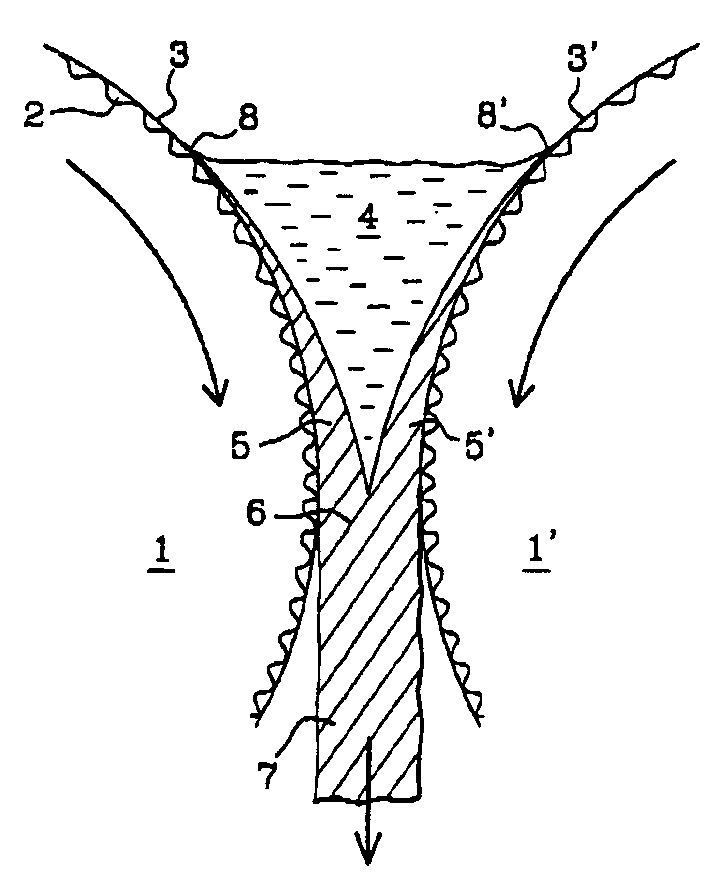
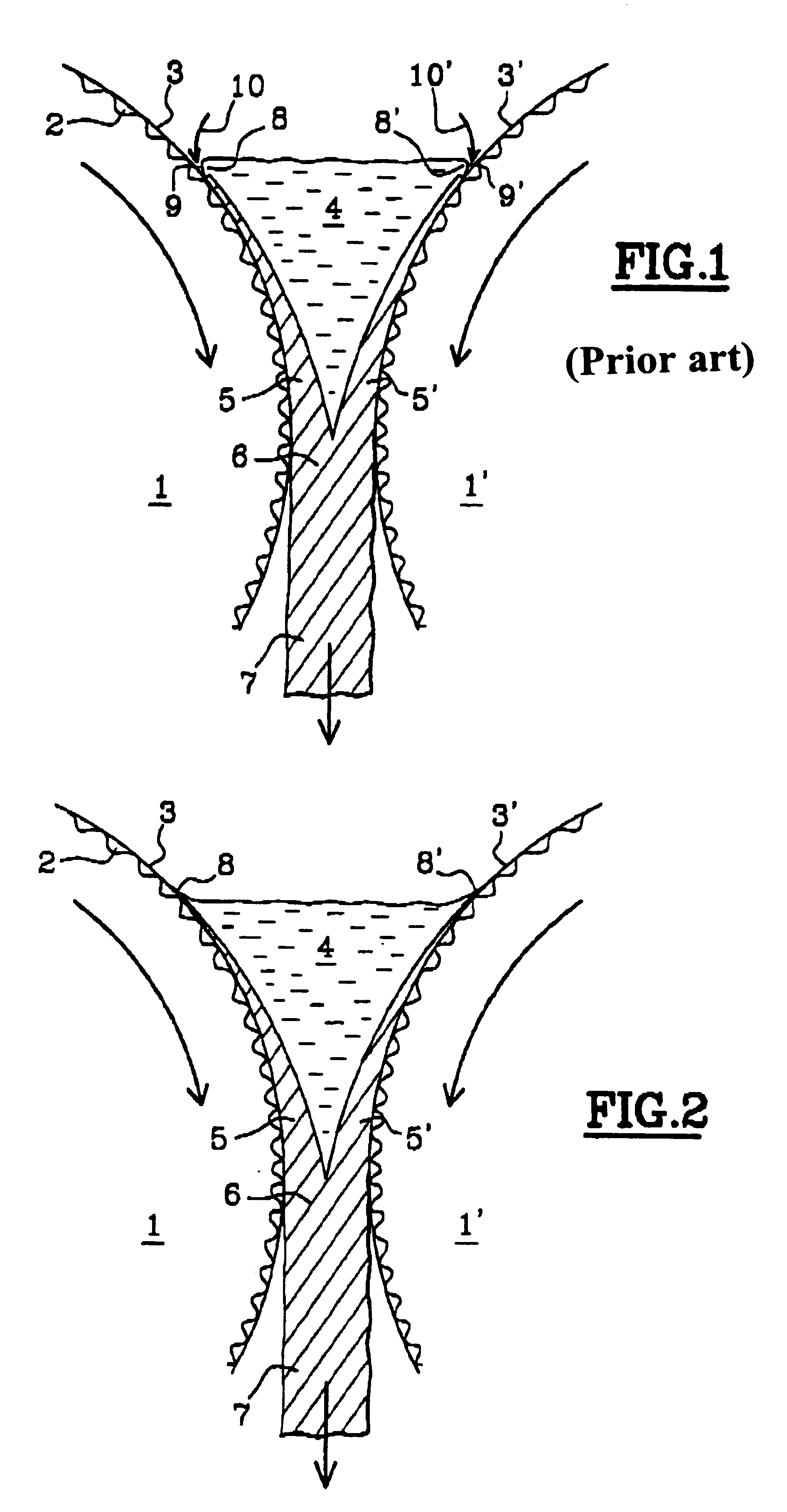
One conventional, rapid and inexpensive method of forming the dimples 2 on the surfaces 3, 3' of the rolls 1, 1' is to blast said surfaces 3, 3' with metal or ceramic balls. By varying the number, materials, diameters and blasting pressure of the balls, it is possible to achieve the desired configurations of said dimples 2. Other methods (using a laser or chemical etching or electrical-discharge machining of the surfaces 3, 3', or marking of the surfaces 3, 3' by knurling) are also conceivable.

Problems solved by technology

However, the industrial application of twin-roll casting to carbon steels cannot be envisaged in an acceptable manner unless it is possible to obtain, in a constant manner, a strip surface quality sufficient for the subsequent treatments undergone by this strip (cold rolling operations, surface treatments, etc) to be possible and to result in the formation of products free of unacceptable defects.
However, this solution complicates the preparation of the rolls compared with the more conventional methods of preparation and, under its optimum conditions, limits the field of application of the cast products to those in which the high sulfur content of the metal is tolerable.

Method used


Image

  • Process for manufacturing carbon-steel strip by twin-roll continuous casting, product produced and apparatus
  • Process for manufacturing carbon-steel strip by twin-roll continuous casting, product produced and apparatus
  • Process for manufacturing carbon-steel strip by twin-roll continuous casting, product produced and apparatus

Examples


Embodiment Construction

By way of example, mention may be made of the case of the casting of strip 2.6 mm in thickness, made of a steel having the composition: C=0.042%; Mn=0.816%; P=0.006%; S=0.005%; Si=0.220%; Al=0.002%; Ni=0.066%; Cr 0.126%; Cu=0.085%; N=0.0058%. The roughness of the rolls was defined by an Ra of 21 .mu.m and an Rz of 92 .mu.m, these being obtained by blasting with steel balls. The compositional and roughness characteristics were therefore in accordance with the invention (particularly the %Mn / %Si ratio was equal to 3.7). When, according to the invention, the surface of the liquid metal was inerted by pure nitrogen or by a 50 / 50% nitrogen / argon mixture, no crazes on the surface of the strip were observed. On the other hand, inerting with 100% argon caused crazes to appear, although these were relatively few in number.

In addition, a 2.6 mm thick strip, whose composition was: C=0.0426%; Mn=0.303%; P=0.004%; S=0.0007%; Si=0.186%; Al=0.003%; Ni=0.035%; Cr=0.075%; Cu=0.031 %; N=0.0044%, for ...


PUM

PropertyMeasurementUnit
Fractionaaaaaaaaaa
Fractionaaaaaaaaaa
Fractionaaaaaaaaaa

Abstract

A process for manufacturing carbon-steel strip having a thickness of less than or equal to 10 mm directly from liquid steel, by casting said liquid steel between the lateral surfaces, made of copper or copper alloy, of two internally cooled rotating horizontal rolls.

Description

1. Field of the InventionThe invention relates generally to the continuous casting of metal. It relates more particularly to the casting of thin carbon-steel strip on plants of the type known as "twin-roll casters".2. Discussion of the BackgroundConsiderable progress has been made in recent years in the development of processes for casting thin steel strip directly from liquid metal. The process mainly used at the present time is the casting of said liquid metal between two internally cooled rolls, rotating about their horizontal axes in opposite directions and placed opposite each other, the minimum distance between their surfaces being approximately equal to the thickness that it is desired to confer on the cast strip (for example a few mm). The casting space containing the liquid steel is defined by the lateral surfaces of the rolls, on which surfaces the strip starts to solidify, and by side closure plates made of refractory, which are applied against the ends of the rolls. The ...

Claims


Application Information

Patent Timeline
IPC IPC(8): B22D11/06B22D11/00B22D11/12B22D11/128C22C38/00C22C38/50
CPCB22D11/0622B22D11/0651
Inventor POIRIER, FRAN.CEDILLA.OISCOMMARIEU, FRAN.CEDILLA.OISEMARCHIONNI, CHRISTIANVICENTE, PATRICEFARAL, MICHELSELARIES, JACQUES
Owner SOLLAC (SA)
Learn More