
Dry polymer and oxide veil removal for post etch cleaning

a technology of oxide veil and etching, which is applied in the direction of electrical equipment, decorative surface effects, decorative arts, etc., can solve the problems of veils, metal oxides, other materials to form on tungsten, and other materials to be removed during etching, and overcome the disadvantages associated with etching

Inactive Publication Date: 2002-11-12
CHANGXIN MEMORY TECH INC
View PDF5 Cites 26 Cited by
  • Summary
  • Abstract
  • Description
  • Claims
  • Application Information

AI Technical Summary

Benefits of technology

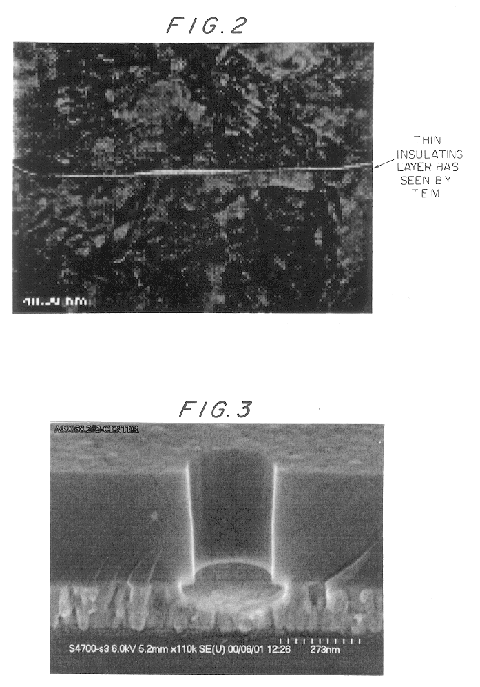
A further object of the present invention is to provide a dry process for removal of polymer and oxide veils from sidewalls of vias and on the interface of a tungsten layer of a semiconductor following oxide etch of an interlevel dielectric in a manner so as to avoid the high contact resistance when an insulator interface is not removed from the tungsten surface and to limit the attack on tungsten to avoid unacceptable tungsten loss.
A yet further object of the present invention is to provide improved C1 contact adhesion after C1 polymer removal to obtain a better surface for the tungsten contact to adhere to, as a result of the undercut of the C1 via.

Problems solved by technology

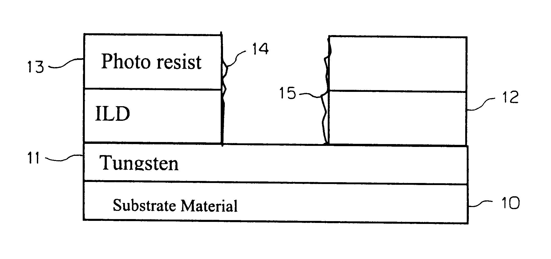
Unfortunately, the etch process causes organic-metal oxides, veils, and other materials to form on the tungsten as well as on the sidewalls of the vias.
Removal of these veil materials has historically been accomplished using wet chemistries and therefore encumbered by the disadvantages associated with these wet chemistries.
Nevertheless, when the resist is stripped using known plasma based or chemical based processes, these processes do not remove the veils formed during the etch.

Method used


Image

  • Dry polymer and oxide veil removal for post etch cleaning
  • Dry polymer and oxide veil removal for post etch cleaning
  • Dry polymer and oxide veil removal for post etch cleaning

Examples


example

Veil Removal

Typical Tool Configuration

The veil removal is done in a vacuum chamber using microwave downstream plasma and reactive ion etching capabilities operating at radio frequencies not limited to but typically 13.56 mHz. The wafers are positioned on a heated platen for improved process control. Process gases for deveiling include fluorine based gases (CF.sub.4, NF.sub.3) and reducing gases such as forming gas (N.sub.2 [100%-X%} / H.sub.2 {X%}, argon, nitrogen or helium.

The process is restricted between two device failure criteria. First is the oxidation of the tungsten and second is the attack on the tungsten at elevated temperatures.

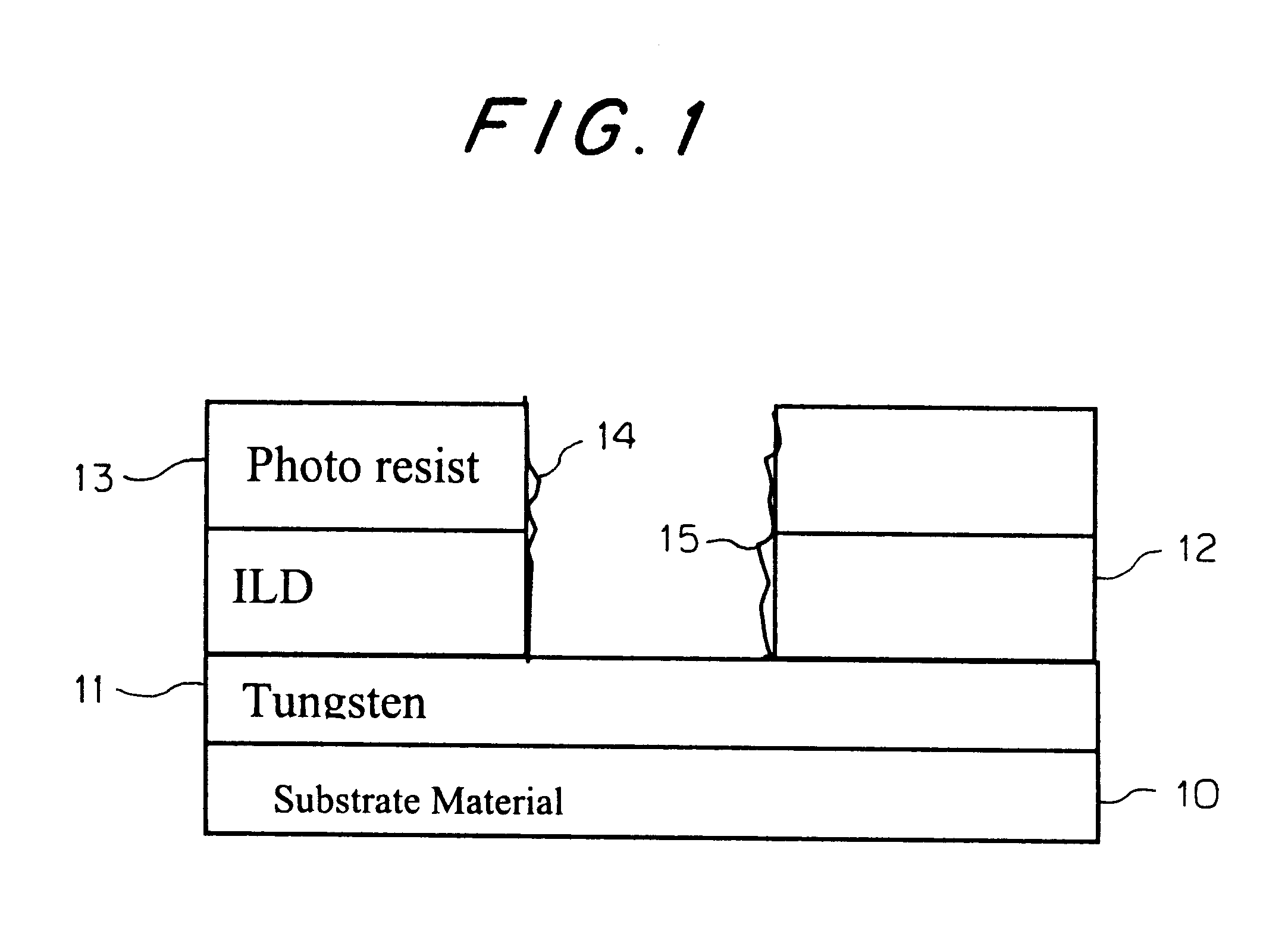
Boundary Condition 1: Interfacial Insulator Penetration. At high gas flows there exists a region of oxidation of the tungsten which inhibits the contact resistance from 2.times. to 1000.times..

Boundary Condition 1 is sensitive to the flow of total reactants, fluorine source (NF.sub.3 or CF.sub.4); power and clean time. This process boundary condition...


PUM

PropertyMeasurementUnit
temperatureaaaaaaaaaa
poweraaaaaaaaaa
poweraaaaaaaaaa

Abstract

In a process of preparing a via in a semiconductor substrate wafer in which vias are landed on tungsten, and in which resist is stripped using plasma or chemical based processes that do not remove the veils formed during the etch, the improvement of concurrently removing veil material, controlling the interface of the tungsten, and stripping the resist, comprising:a) depositing and patterning tungsten on a substrate;b) depositing an oxide as an interlevel dielectric on the tungsten;c) patterning the oxide using photolithography and a photoresist;d) etching the oxide using a plasma generated etching method in which veils made up of metals, carbon based materials and oxide based materials are formed on the tungsten and sidewalls of the vias; ande) stripping the resist using a dry polymer removal method employing process gases and reducing gases to concurrently cause resist stripping, removal of the veils, and control of the tungsten interface.

Description

1. Field of InventionThe invention relates to a dry method for removing polymer and oxide veils for vias disposed on a Tungsten layer resulting from etching and controlling or partially removing the tungsten base or interface layer to create an undercut of the via to provide better plug adhesion when the via is filled.2. Description of the Prior ArtDuring the making of a semiconductor chip structure in which a tungsten layer is deposited on a substrate material, and in which an oxide is deposited on the tungsten layer as an interlevel dielectric (ILD), and on which a photoresist is subsequently placed on the interlevel dielectric, followed by etching and photolithographic resist removal, veils are created in the vias and on the tungsten layer. This is so because the vias are etched through insulators and the etch progress stops on the tungsten.Unfortunately, the etch process causes organic-metal oxides, veils, and other materials to form on the tungsten as well as on the sidewalls o...

Claims


Application Information

Patent Timeline
Patent Type & Authority Patents(United States)
IPC IPC(8): H01L21/02H01L21/70H01L21/768H01L21/311
CPCH01L21/02063H01L21/31116H01L21/76814H01L21/76838H01L21/31138
Inventor XU, HANSHEN, AMY YINGCLARK, JR., PHILLIP GERARD
Owner CHANGXIN MEMORY TECH INC
Learn More