
Rocket motor joint construction including thermal barrier

a technology of thermal barrier and rocket motor, which is applied in the direction of vessel construction, marine propulsion, ornamental textile articles, etc., can solve the problems of affecting the changing the properties and/or dimensions of the casing structure, and not being able to verify the integrity of the seal arrangement. , to achieve the effect of enhancing the sealing effect, enhancing certain functions or properties of the thermal barrier, and facilitating assembly of rocket motor sections

Inactive Publication Date: 2002-09-10
NASA
View PDF26 Cites 36 Cited by
  • Summary
  • Abstract
  • Description
  • Claims
  • Application Information

AI Technical Summary

Benefits of technology

It is a further object of the present invention to provide an improved thermal barrier for rocket motors which can withstand rocket motor firing temperatures for a longer period of time.
In still further embodiments of the invention materials such as copper or aluminum can be added to the thermal barrier structure to achieve various desired effects. For example if the core and / or one or more inner braid layers of the thermal barrier is formed of one of such metals, the latent heat of fusion of the metal is utilized so that the metal is sacrificed to maintain a high temperature differential across the thermal barrier. In this way the thermal barrier may withstand prolonged exposure to the hot gases of the rocket motor, providing additional time before the thermal barrier is affected. While molten metal may be deposited within the carbon braids of the thermal barrier, this will also provide the additional advantage of reducing the porosity of the thermal barrier when high porosity of the barrier is no longer desired. That is for example, at a time after initial pressurization of the primary and secondary O-ring seals and when less flow through the thermal barrier is desired, or in circumstances where pressure is being lost through the O-ring seals and it is desirable to minimize flow to prevent erosion and charring of the O-ring seals and possible joint damage. Numerous other advantages of the thermal barrier and joint structure of the invention will be apparent from the following description.

Problems solved by technology

Occasionally, seals have experienced charring due to parasitic leakage paths that open up in the joint-fill compounds during rocket operation.
Reusable rocket sections present additional design constraints in that after each firing the casings have experienced considerable stresses and have been exposed to environmental conditions which may change the properties and / or dimensions of the casing structure.
This is in addition to the initial design constraints for the joint structure and the seals therein which may experience relative movement between casing sections due to vibration or the thrust forces produced by the rocket motor.
An additional design constraint imposed upon joint structures including the primary and secondary O-ring seal arrangement is that once the casing sections are assembled, the seals are buried within the structure at a location which is highly tolerant to the physical stresses imposed during motor firing, but not readily accessible to verify the integrity of the seal arrangement.
However existing materials have proven unsuitable for this purpose.

Method used


Image

  • Rocket motor joint construction including thermal barrier
  • Rocket motor joint construction including thermal barrier
  • Rocket motor joint construction including thermal barrier

Examples


Embodiment Construction

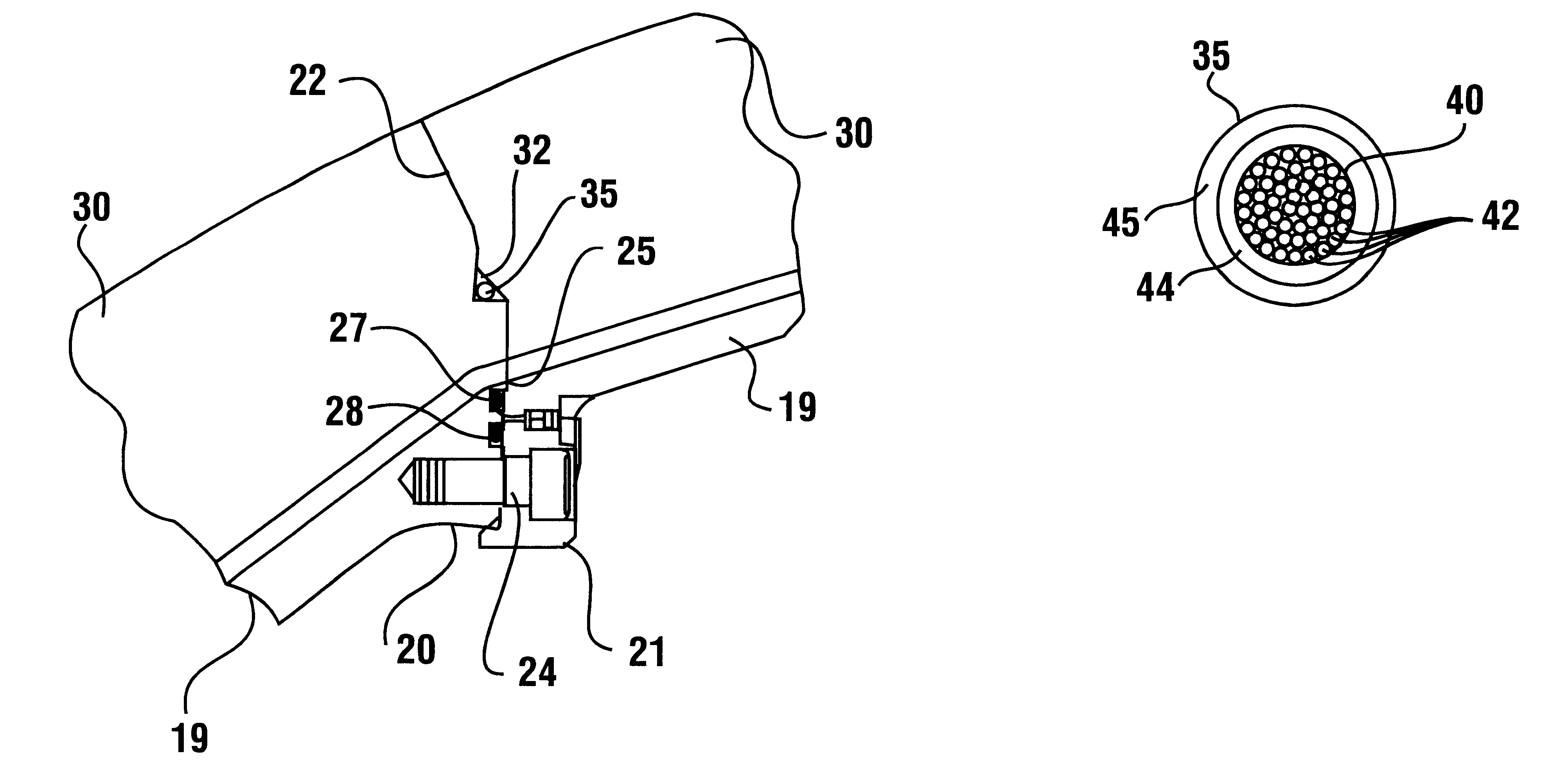
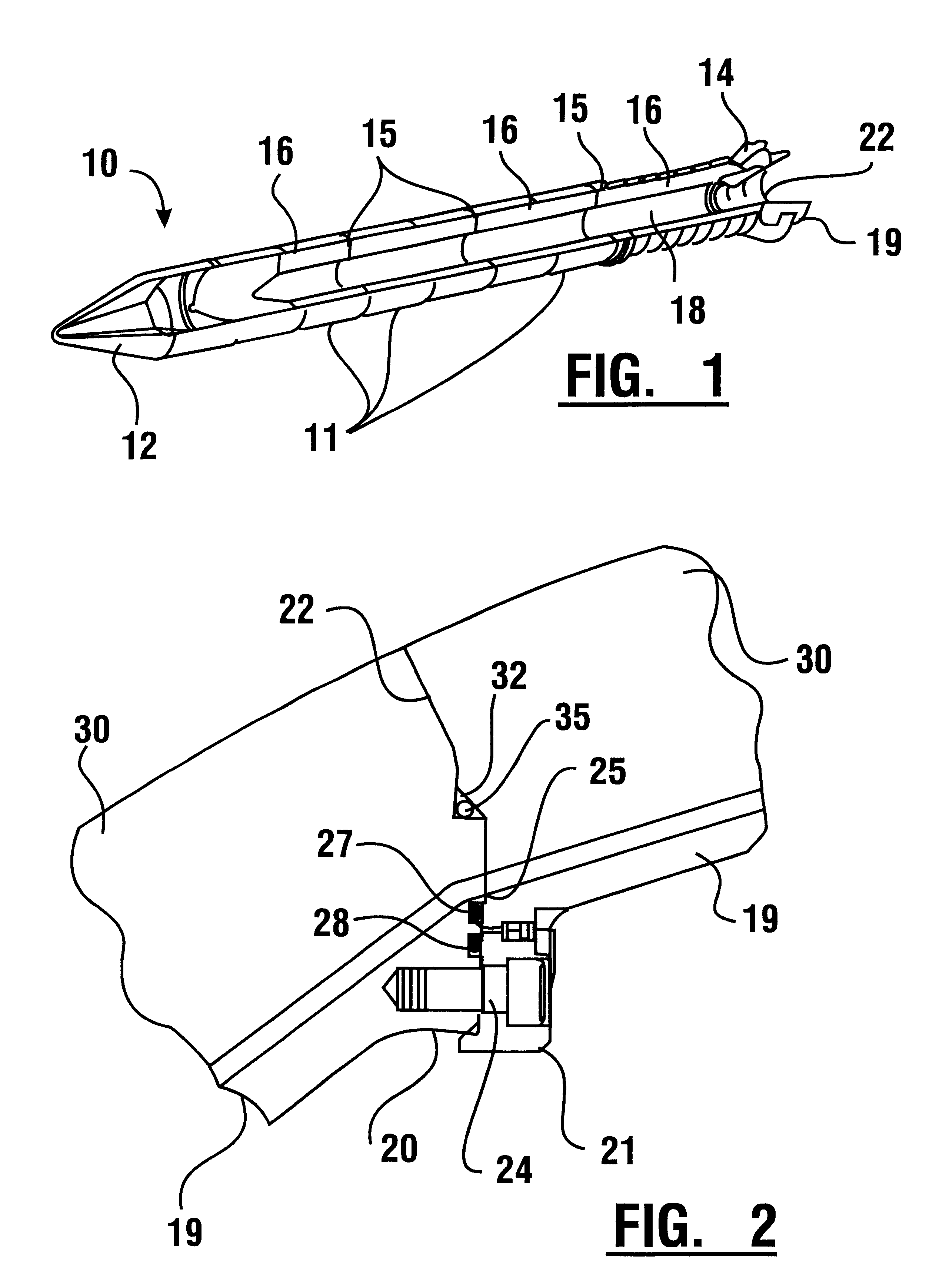
Referring now to the drawings there is shown in FIG. 1 a solid rocket motor 10 in which the teachings of an exemplary embodiment of the present invention are applied. Rocket motor 10 is segmented and comprised of a plurality of generally cylindrical casings or casing sections 11. A frustum or nose fairing 12 is located at the forward end. A nozzle 14 and thrust vector control system are located at the aft end. The casings 11 are axially aligned and joined to one another through casing joints 15 therebetween. The casings are lined inside with tubular sections of rocket propellant 16, forming a central chamber 18 for enabling axial flow of rocket combustion gases during the rocket burn. Rocket motor nozzle 14 is segmented and comprised of a plurality of generally cylindrical or conical nozzle segments or sections 19.

In FIG. 2 is an enlarged view of a part of a lower casing joint 22 between adjacent nozzle segments 19. The joint 22 extends through mating flanges 20, 21 of forward and a...


PUM

PropertyMeasurementUnit
braid angleaaaaaaaaaa
temperaturesaaaaaaaaaa
peak temperaturesaaaaaaaaaa

Abstract

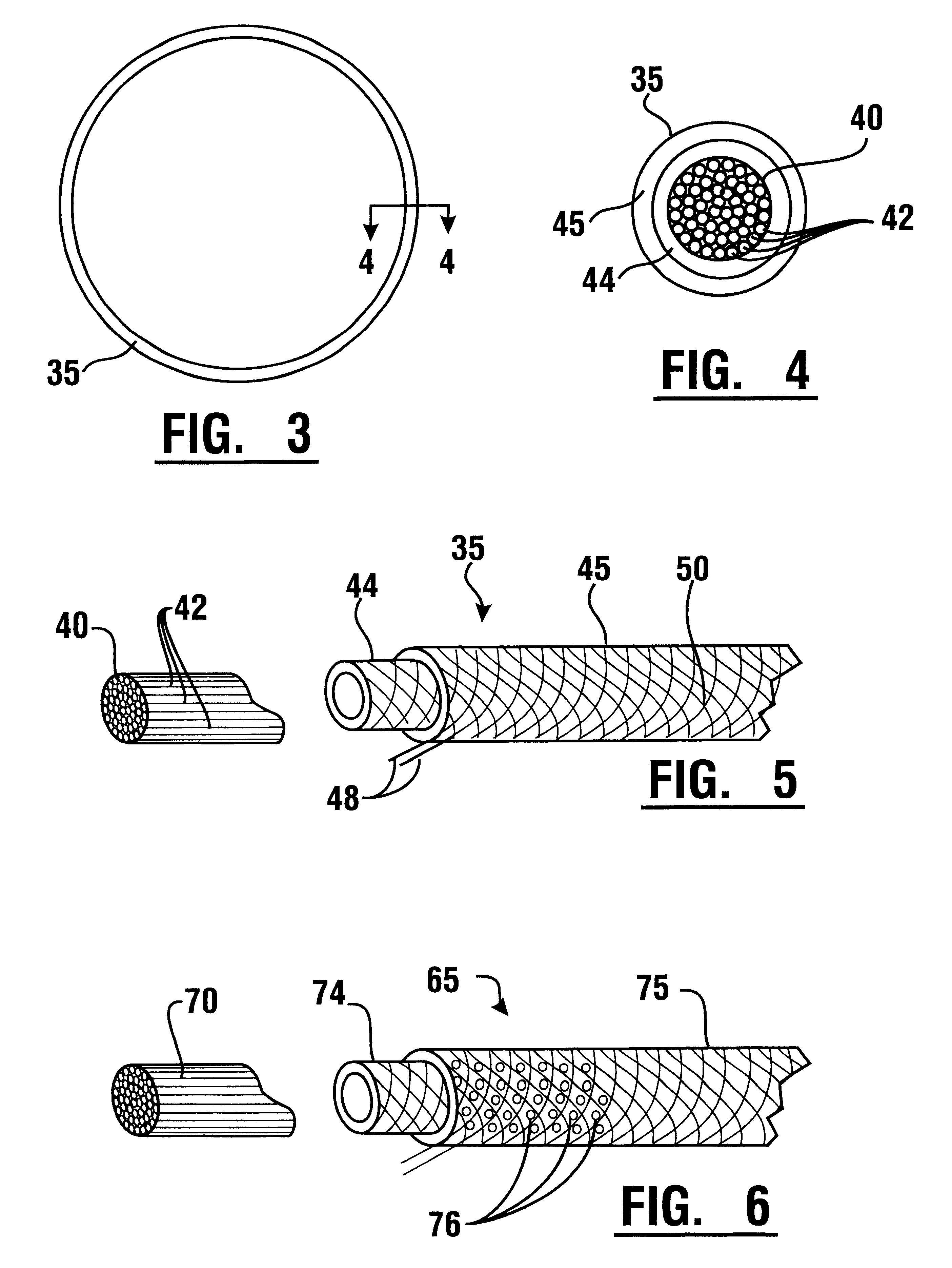
A thermal barrier for extremely high temperature applications consists of a carbon fiber core and one or more layers of braided carbon fibers surrounding the core. The thermal barrier is preferably a large diameter ring, having a relatively small cross-section. The thermal barrier is particularly suited for use as part of a joint structure in solid rocket motor casings to protect low temperature elements such as the primary and secondary elastomeric O-ring seals therein from high temperature gases of the rocket motor. The thermal barrier exhibits adequate porosity to allow pressure to reach the radially outward disposed O-ring seals allowing them to seat and perform the primary sealing function. The thermal barrier is disposed in a cavity or groove in the casing joint, between the hot propulsion gases interior of the rocket motor and primary and secondary O-ring seals. The characteristics of the thermal barrier may be enhanced in different applications by the inclusion of certain compounds in the casing joint, by the inclusion of RTV sealant or similar materials at the site of the thermal barrier, and / or by the incorporation of a metal core or plurality of metal braids within the carbon braid in the thermal barrier structure.

Description

This invention relates to sealing devices and more particularly to a rocket motor joint construction which includes a thermal barrier structure in conjunction with elastomeric primary and secondary O-ring seals between casings of a solid rocket motor.Assembly joints of current solid rocket motor cases are generally sealed using high performance, elastomeric O-ring seals. The 5500.degree. F. propulsion gases commonly produced during the relatively short firing interval of the rocket motors are kept a safe distance away from compounds are used to fill insulation gaps leading to the seals to prevent a flowpath of propulsion gases to the seals.Normally, these two stages of protection are enough to prevent a direct flowpath of the 900-psi hot gases from reaching the seals. Occasionally, seals have experienced charring due to parasitic leakage paths that open up in the joint-fill compounds during rocket operation. Inspection during disassembly of Space Shuttle solid rocket motor nozzle jo...

Claims


Application Information

Patent Timeline
Patent Type & Authority Patents(United States)
IPC IPC(8): F16J15/06F16J15/10
CPCF16J15/065F16J15/104Y10S277/938D04C1/02D10B2403/0243D10B2505/06
Inventor STEINETZ, BRUCE M.DUNLAP, JR., PATRICK H.
Owner NASA
Learn More