
Color cathode ray tube with curved shadow mask having central recessed portions

a color cathode ray tube and shadow mask technology, applied in the field of color cathode ray tubes, can solve the problems of local deviation of distance, easy occurrence of color purity deterioration, and deterioration of color purity, so as to reduce the deviation of beam landing and color purity deterioration, and increase the holding strength of the curved surfa

Inactive Publication Date: 2002-08-20
KK TOSHIBA
View PDF15 Cites 6 Cited by
  • Summary
  • Abstract
  • Description
  • Claims
  • Application Information

AI Technical Summary

Benefits of technology

The present invention has been contrived in consideration of the above problems, and its object is to provide a color cathode-ray tube which reduces deviation of beam landing and deterioration of color purity by increasing the curved surface holding strength of the shadow mask.
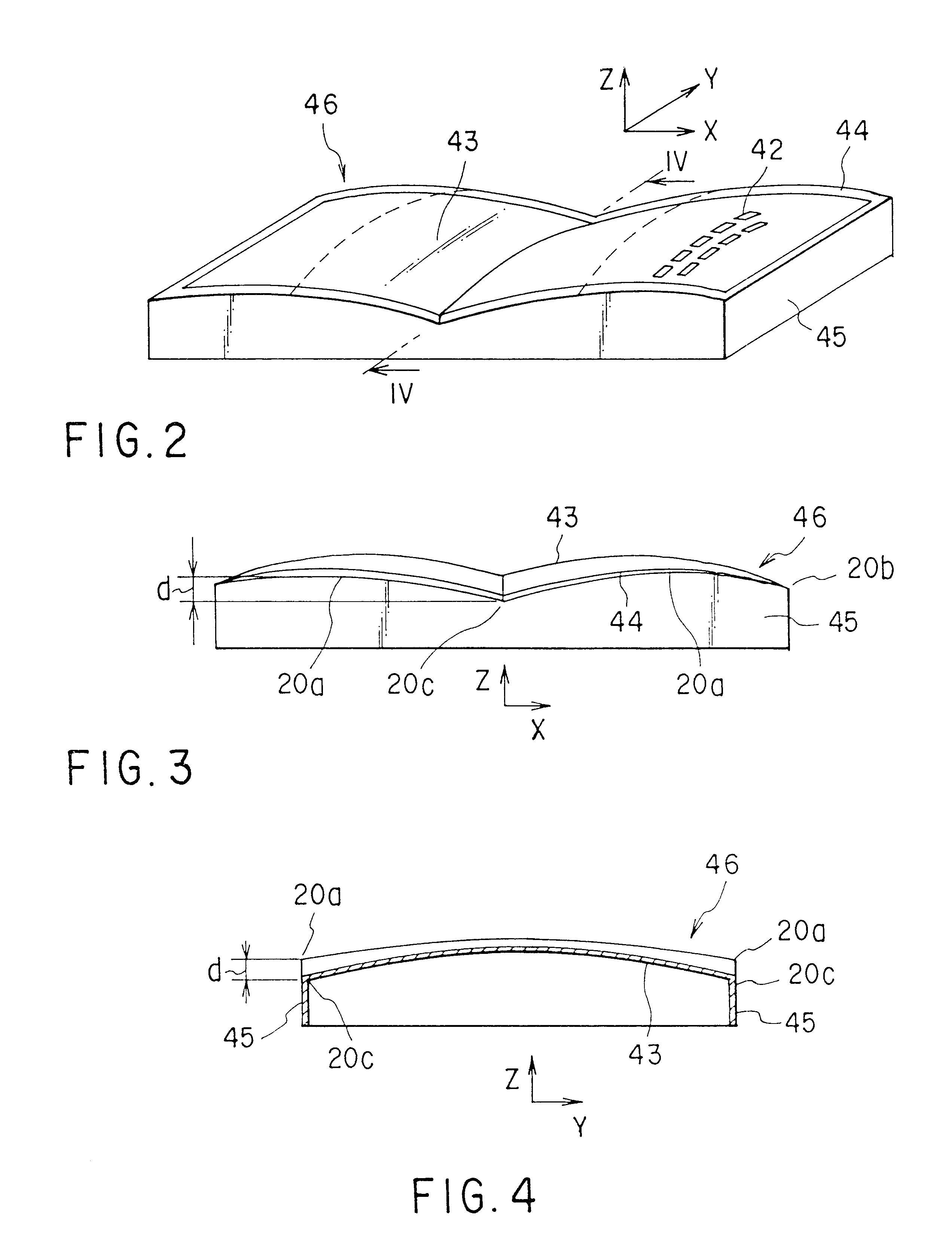
According to the color cathode-ray tube having the above-described structure, the provision of a recess on each of the long sides of the effective surface or the non-aperture portion of the mask main body makes it possible to maintain high-level strength for holding the curved surface of the effective surface of the mask main body even in the case where the radius of curvature of the effective surface of the mask main body has been increased along an increase in the radius of curvature of the external surface of the effective portion of the panel. Therefore, it is possible to provide a color cathode-ray tube which can minimize an occurrence of deterioration of color purity by restricting local deformation of a shadow mask in the process of manufacturing the shadow mask, thermal deformation of the shadow mask in the process of manufacturing the color cathode-ray tube, or oscillation due to the sound from the speaker when the color cathode-ray tube has been built into a TV set. Particularly, when the present invention is applied to a color cathode-ray tube having an aspect ratio of 16 to 9, the curved-surface holding strength can be increased in good balance over the whole surface of the mask main body. Thus, it is possible to structure a color cathode-ray tube capable of providing satisfactory picture quality by minimizing an occurrence of howling of color purity.
Thus, at these portions near the short axis ends (those portions near the long sides), the radius of curvature of the mask main body in the short axis direction has a sufficient value for maintaining the curved surface holding strength, and at the other portion of the mask main body, the radius of curvature is larger than those at the short axis end portions, so that it is possible to delete an influence of the recess at a main region of the effective portion.

Problems solved by technology

However, the increasing of the radius of curvature of the effective surface of the mask main body lowers the strength for holding the curved surface (hereinafter, referred as a curved surface holding strength) of the shadow mask, and easily causes local deformation of the shadow mask in the process of manufacturing the shadow mask and thermal deformation of the shadow mask in the process of manufacturing a color cathode-ray tube, resulting in a deviation of beam landing which leads to an occurrence of deterioration of color purity.
Further, when the color cathode-ray tube is built into a TV set, sound generated from the speaker oscillates the shadow mask, which leads to an easy occurrence of deterioration of color purity.
However, when reinforcing beads are provided on the effective surface having a large radius of curvature in an attempt to obtain a sufficient curved surface holding strength, stepped portions formed as a result causes a local deviation of the distance between the inner surface of the effective portion of the panel and the effective surface of the mask main body from a permissible range of values for the distance.
Accordingly, an image of the stepped portions appear on the screen and this extremely deteriorates the picture quality.
However, the provision of reinforcing beads of this height on the shadow mask having a large radius of curvature of the effective surface can not sufficiently increase the curved surface holding strength.

Method used


Image

  • Color cathode ray tube with curved shadow mask having central recessed portions
  • Color cathode ray tube with curved shadow mask having central recessed portions
  • Color cathode ray tube with curved shadow mask having central recessed portions

Examples


Embodiment Construction

A color cathode-ray tube according to an embodiment of the present invention will be explained in detail with reference to the drawings.

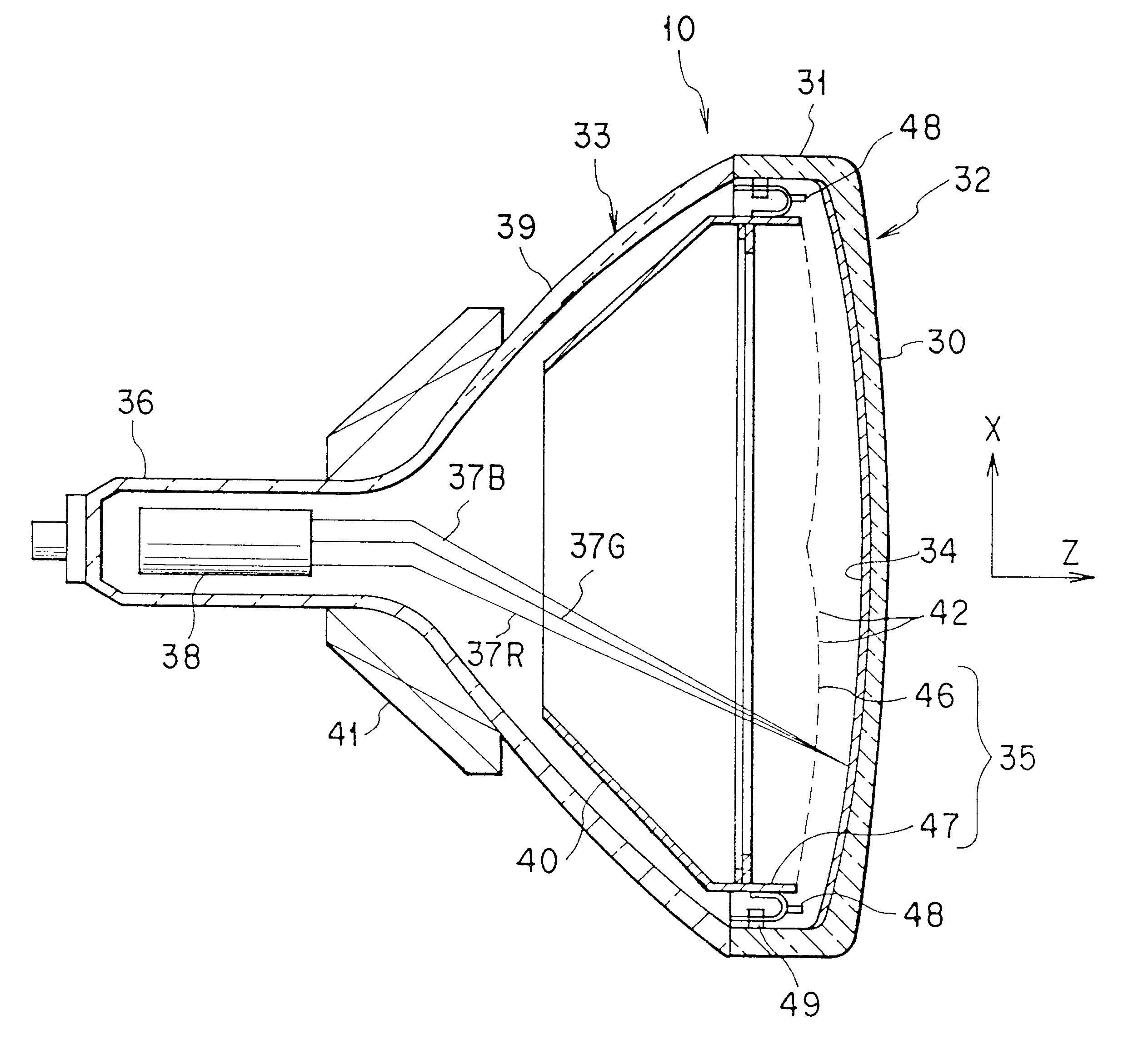
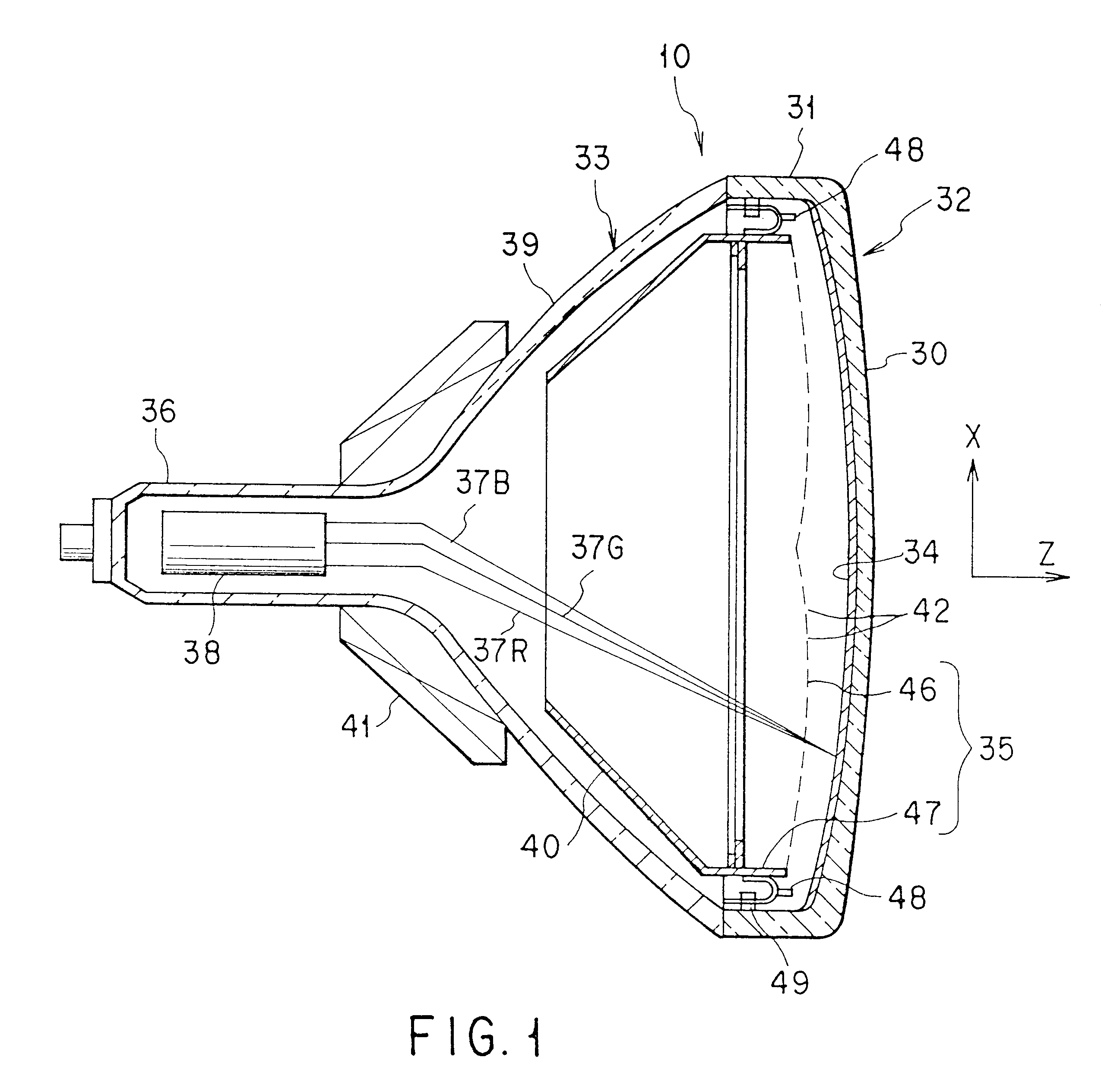
As shown in FIG. 1, a color cathode-ray tube has a vacuum envelope 10. This vacuum envelope 10 includes a substantially rectangular panel 32 having an effective portion 30 of a curved surface and a skirt portion 31 provided on the periphery of this effective portion, and a funnel 33 connected to the skirt portion. On the inner surface of the effective portion 30 of the panel 32 is formed a phosphor screen 34 including a black color non-light emitting substance layers and a three-color phosphor layers buried in gaps of the black non-light emitting substance layers. Inside the panel 32, there is disposed a substantially rectangular shadow mask 35 facing the phosphor screen 34. Within a neck 36 of the funnel 33 is arrange an electron gun 38 for emitting three electron beams. Inside a large diameter portion 39 of the funnel 33 is disposed an inner shiel...


PUM


Abstract

A shadow mask of a color cathode-ray tube has a substantially rectangular mask main body and a substantially rectangular mask frame fixed to a skirt portion of the mask main body. The mask main body has a curved effective surface formed with a large number of electron-beam passage apertures and opposing the phosphor screen, a non-aperture portion surrounding the outer periphery of this effective surface, and a skirt portion formed in a bent on the outer periphery of the non-aperture portion. The mask main body has a long axis extending in a horizontal direction and crossing with a tube axis, and a short axis extending in a vertical direction and crossing with both the tube axis and the long axis. The effective surface and the non-aperture portion of the mask main body are formed in a curved surface having a radius of curvature in the short axis direction. At each long side of the mask main body, each end portion of the short axis of the effective surface and the non-aperture portion is recessed from any other adjacent part, in a direction leaving from the phosphor screen along the tube axis. The radius of curvature in a short axis direction near the short axis of the effective surface and the non-aperture portion of the mask main body is smaller than the radius of curvature in the short axis direction at other parts.

Description

The present invention relates to a color cathode-ray tube, and relates, more particularly, to a color cathode-ray tube with an increased holding strength of a curved surface of a shadow mask to reduce deviation of beam landing.In general, a color cathode-ray tube has a vacuum envelope which includes a substantially rectangular panel having an effective portion formed of a curved surface and a skirt portion provided on the periphery of the effective portion, and a funnel connected to the skirt portion. On the inner surface of the effective portion of the panel is formed a phosphor screen consisting of black non-light emitting substance layers and three-color phosphor layers buried in gap of the black non-light emitting substance layers. Inside the panel is disposed a substantially rectangular shadow mask facing the phosphor screen. Within a neck of the funnel is disposed an electron gun for emitting three electron beams. Inside a large diameter portion of the funnel, there is dispose...

Claims


Application Information

Patent Timeline
Patent Type & Authority Patents(United States)
IPC IPC(8): H01J29/07
CPCH01J29/07H01J2229/0794
Inventor AKOH, NOBUHIKOSHIMIZU, NORIONAKAGAWA, SHINICHIROMASHIMO, TAKUYAINOUE, MASATSUGU
Owner KK TOSHIBA
Learn More