
Method for inserting spinal implants and for securing a guard to the spine

Inactive Publication Date: 2002-08-20
WARSAW ORTHOPEDIC INC
View PDF84 Cites 412 Cited by
  • Summary
  • Abstract
  • Description
  • Claims
  • Application Information

AI Technical Summary

Benefits of technology

3. Disc removal--The BAGBY invention requires the complete removal of the disc prior to the drilling step, whereas the present invention eliminates the laborious separate process of disc removal and efficiently removes the disc and prepares the vertebral end plates in a single step.
Alternatively, a second Inner Sleeve may be placed within the Outer Sleeve prior to placing the Trephine over the Long Distractor and within that second sleeve. This second Inner Sleeve would be just greater in its internal diameter than the Long Distractor and just smaller in its outside diameter than the inner diameter of the Outer Sleeve. While it would provide enhanced stability to the Trephine, provision would then need to be made in is the way of large flutes passing longitudinally or obliquely along the outer surface of the Distractor to its barrel portion to accommodate the bony and cartilaginous debris generated during the cutting procedure.

Problems solved by technology

Placing nothing into this space allows the space to collapse which may result in damage to the nerves; or the space may fill with scar tissue and eventually lead to a reherniation.
The use of bone to fill the space is less than optimal in that bone obtained from the patient requires additional surgery and is of limited availability in its most useful form, and if obtained elsewhere, lacks living bone cells, carries a significant risk of infection, and is also limited in supply as it is usually obtained from accident victims.
Furthermore, regardless of the source of the bone, it is only marginal structurally and lacks a means to either stabilize itself against dislodgement, or to stabilize the adjacent vertebrae.
No such device has been found that is medically acceptable.
Furthermore, these devices are limited in that they seek to perform as temporary structural members mechanically replacing the removed vertebrae (not a removed disc), and do not intrinsically participate in supplying osteogenic material to achieve cross vertebrae bony fusion.
In summary, none of these devices are designed to be nor can be used within the disc space.
Moreover, these devices do not replace a damaged disc, and do not intrinsically participate in the generation of a bony fusion.
1. Safety--The present invention provides for a system of completely guarded instrumentation so that all contiguous vital structures (e.g. large blood vessels, neural structures) are absolutely protected. The instrumentation of the present invention also makes overpenetration by the drill impossible. Such overpenetration in the cervical spine, for example, would result in the total paralysis or death of the patient. In the thoracic spine, the result would be complete paraplegia. In the lumbar spine, the result would be paraplegia or a life-threatening perforation of the aorta, vena cava, or iliac vessels.
This is extremely dangerous and the pounding occurs directly over the spinal cord which is precariously vulnerable to percussive injury.
Furthermore, since the BAGBY device is pounded into a smooth hole under great resistance, and lacking any specific design features to secure it, the device is highly susceptible to forceful ejection which would result in great danger to the patient and clinical failure.
Because of the proximity of the spinal cord, spinal nerves, and blood vessels, any implant dislodgement as might occur with the BAGBY device might have catastrophic consequences.
5. Implant stability--Dislodgement of the implant would be a major source of device failure (an unsuccessful clinical result), and might result in patient paralysis or even death.
As discussed, the BAGBY device lacks any specific means of achieving stability and since it is pounded in against resistance to achieve vertebral distraction, and is susceptible to forceful dislodgement by the tendency of the two distracted vertebrae, to return to their original positions squeezing out the device.
Secondly, as the BAGBY device lacks any specific design features to resist sliding, it may actually behave as a third body allowing the translation of the vertebrae relative to the device and to each other.
Thirdly, any device can only provide stability if it remains properly, seated.
Fourthly, it is not pressure alone that causes the collapse of the bone adjacent to the implant, but also bony erosion that is caused by the motion under pressure of the implant against the bone.
Cloward's method of instrumentation was designed for, and limited to, use on the anterior aspect and in the region of the cervical spine only.
As the bone graft to be inserted in Cloward's method was necessarily larger in diameter than the hole drilled, the graft could not be inserted through the drill guide.
Thus Cloward's method and instrumentation was inappropriate for posterior application.
In addition, the failure to provide continuous protection to the delicate neural structures from the instruments, as well as the bony and cartilaginous debris generated during the procedure, made Cloward's method inappropriate for posterior application.
Also, the drill guide described by Cloward could not be placed posteriorly within the spinal canal, as the foot plate would crush the nerves.
Modifying Cloward's drill guide by removing the foot plate completely, would still leave the instrument unworkable as it would then lack stability, and would not be controllable for depth of seating.
While Wilterberger had taken the Cloward concept of circular drilling and dowel fusion and applied it to the lumbar spine from a posterior approach, he had not provided for an improved method, nor had he advanced the instrumentation so as to make that procedure sufficiently safe, and it rapidly fell into disrepute.
1. Failure to protect the surrounding tissues throughout the procedure, specifically, prior to drilling and until after the insertion of the graft;
2. Failure to contain the debris, bony and cartilaginous, generated during the procedure;
3. Failure to optimize the contact of the cylindrical drill hole and bone graft, the mismatch in their diameters resulting in incongruence of fit;
4. Failure to determine the optimal drill size prior to drilling;
5. Failure to determine the optimal amount of distraction prior to drilling;
6. Inability to optimize the amount of distraction so as to restore the normal spatial relationships between adjacent vertebrae;
7. Inability to create sufficient working space within the spinal canal (between the nerve roots and the dural sac) to make the procedure safe;
8. Absent a foot plate on the drill guide, as necessitated by the close tolerances posteriorly, the inability to reliably insure that the drilling is parallel to the vertebral endplates;
9. The inability to insure equal bone removal from the opposed vertebral surfaces; and
The inability to determine within the spinal canal, the proper side by side positioning for dual drill holes.

Method used


Image

  • Method for inserting spinal implants and for securing a guard to the spine
  • Method for inserting spinal implants and for securing a guard to the spine
  • Method for inserting spinal implants and for securing a guard to the spine

Examples


Embodiment Construction

In the preferred embodiment, the disc (D) between adjacent vertebrae (V) is approached via bilateral paired semihemilaminotomies of the adjacent vertebrae. In the preferred embodiment the supraspinous ligament, the interspinous ligament, the spinous process, portions of the lamina, and most of the facet joints are preserved. However, while less desirable, these structures may be removed.

In the preferred method, a bilateral partial nuclear discectomy is then performed through bilateral openings created through the posterior aspect of the annulus fibrosus. While considered less desirable, disc excision can be delayed and performed simultaneously with the vertebral bone resection during the drilling procedure. Starting on the first side a dural nerve root retractor is placed such that the dural sac and lower nerve root are retracted medially allowing exposure to one side of a portion of two adjacent vertebral bodies and the interposed disc posteriorly.

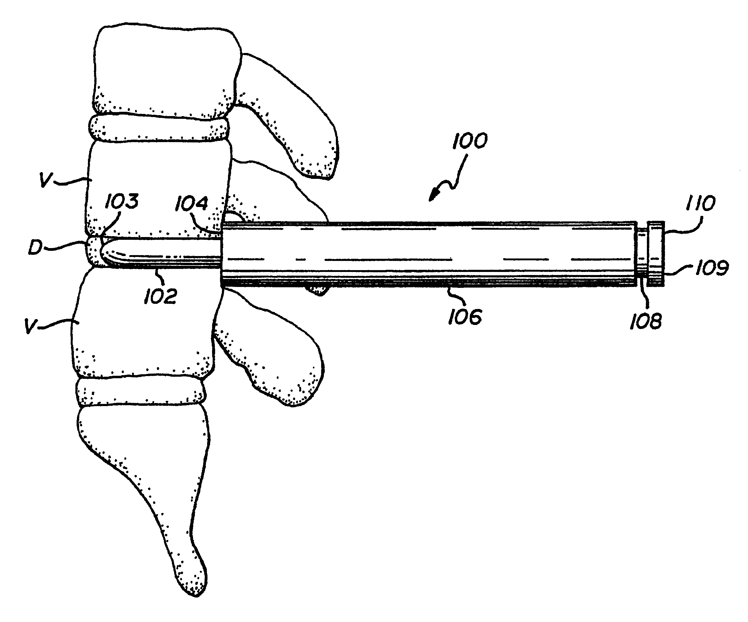
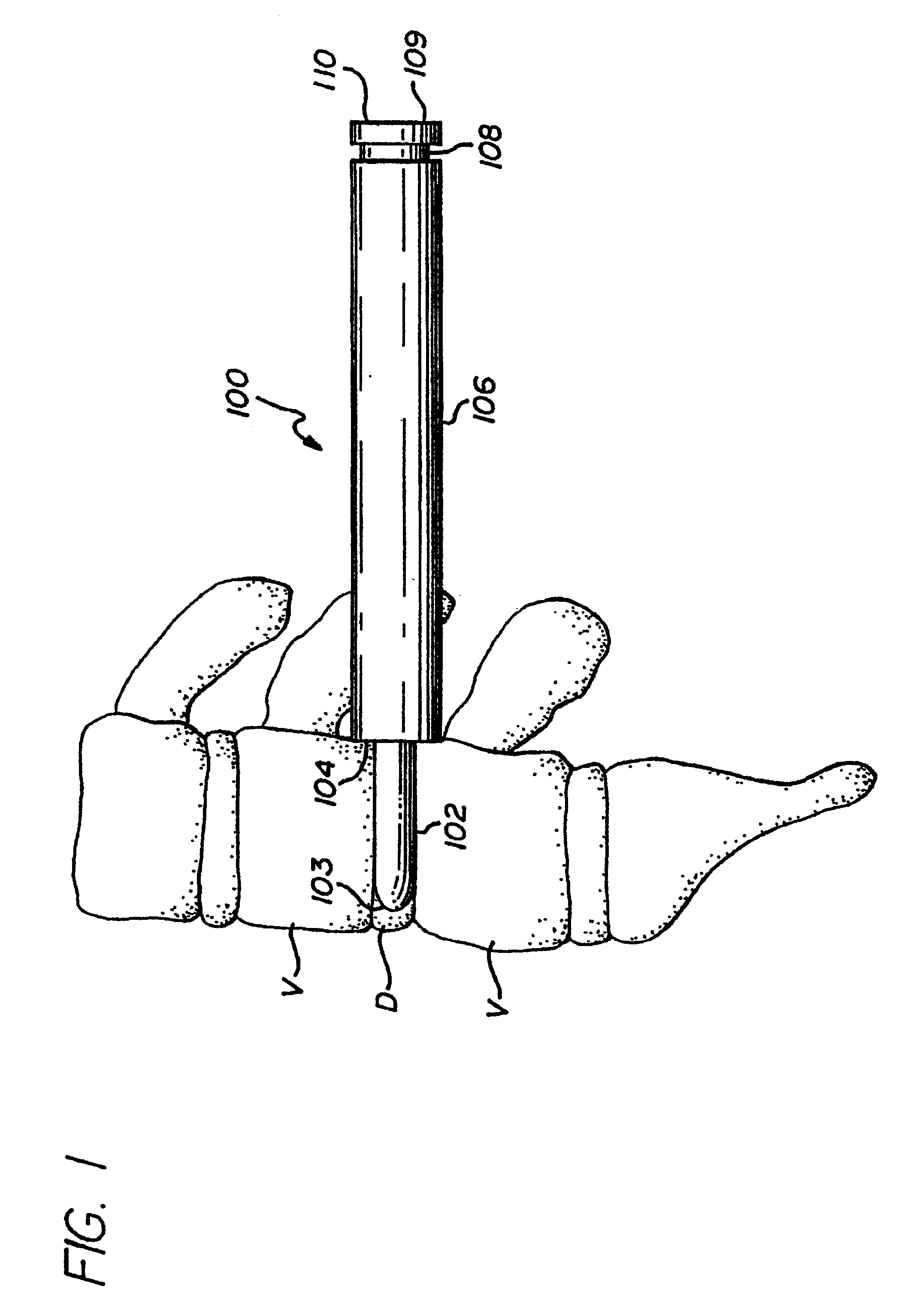
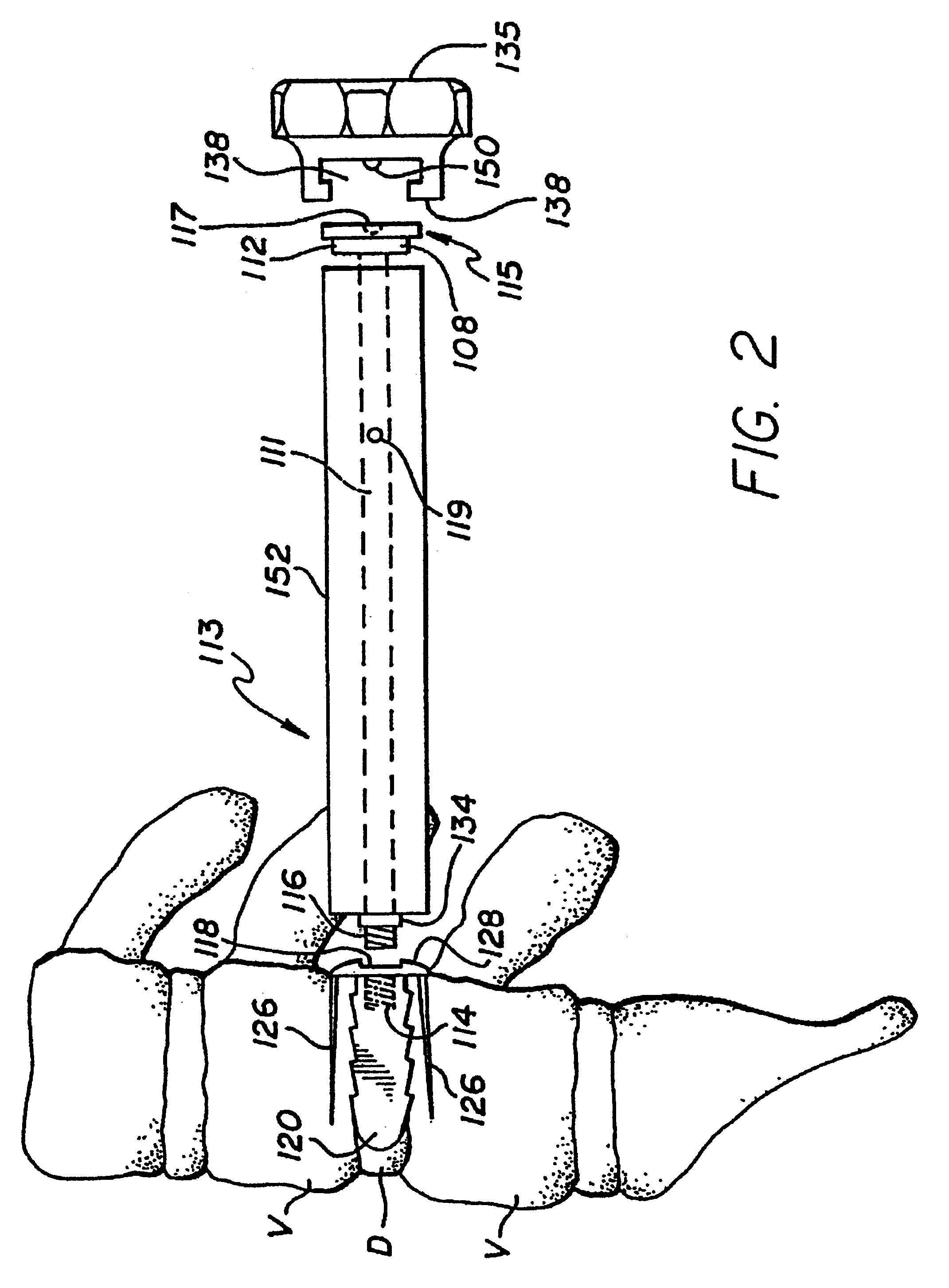
Referring now to FIG. 1, preferabl...


PUM


Abstract

Apparatus and a method of inserting spinal implants is disclosed in which an intervertebral space is first distracted, a hollow sleeve having teeth at one end is then driven into the vertebrae adjacent that disc space. A drill is then passed through the hollow sleeve removing disc and bone in preparation for receiving the spinal implant which is then inserted through the sleeve.

Description

1. Field of the InventionThe present invention relates to artificial fusion implants to be placed into the intervertebral space left remaining after the removal of a damaged spinal disc and specifically to the apparatus for and method of, inserting the implants.2. Description of the Prior ArtFor the purpose of achieving long term stability to a segment of injured spine, a fusion (the joining together of two or more bones via a continuous bridge of incorporated bone) may be performed. Well-known to those skilled in such art is the interbody fusion wherein the disc is partially excised and bone placed within that space previously occupied by that disc material (between adjacent vertebrae) for the purpose of restoring a more normal spatial relationship, and to provide for stability; short term by mechanical support, and long term by the permanent cross bonding of bone from vertebra to vertebra. For fusion to occur within the disc space, it is necessary to prepare the vertebrae to be fu...

Claims


Application Information

Patent Timeline
IPC IPC(8): A61B17/88A61B17/02A61B17/58A61B17/16A61B17/17A61B17/70A61F2/44A61F2/46
CPCA61B17/025A61B17/1671Y10T407/1964A61B2017/0256Y10S623/908A61B17/1757A61B17/8888A61F2/446A61F2/4611A61B17/1655A61B17/32A61B17/3468A61B17/8877
Inventor MICHELSON, GARY KARLIN
Owner WARSAW ORTHOPEDIC INC
Learn More