
Optical information medium and its fabrication process

a technology of optical information medium and fabrication process, which is applied in the direction of photomechanical equipment, instruments, transportation and packaging, etc., can solve the problems of medium warping, difficult to form the light-transmitting layer used for this structure, and difficulty in achieving uniform curing so as to reduce the optical heterogeneity of the light-transmitting layer in the thickness direction, prevent warping of the optical information medium, and uniform thickness

Inactive Publication Date: 2002-06-25
TDK CORPARATION
View PDF6 Cites 9 Cited by
  • Summary
  • Abstract
  • Description
  • Claims
  • Application Information

AI Technical Summary

Benefits of technology

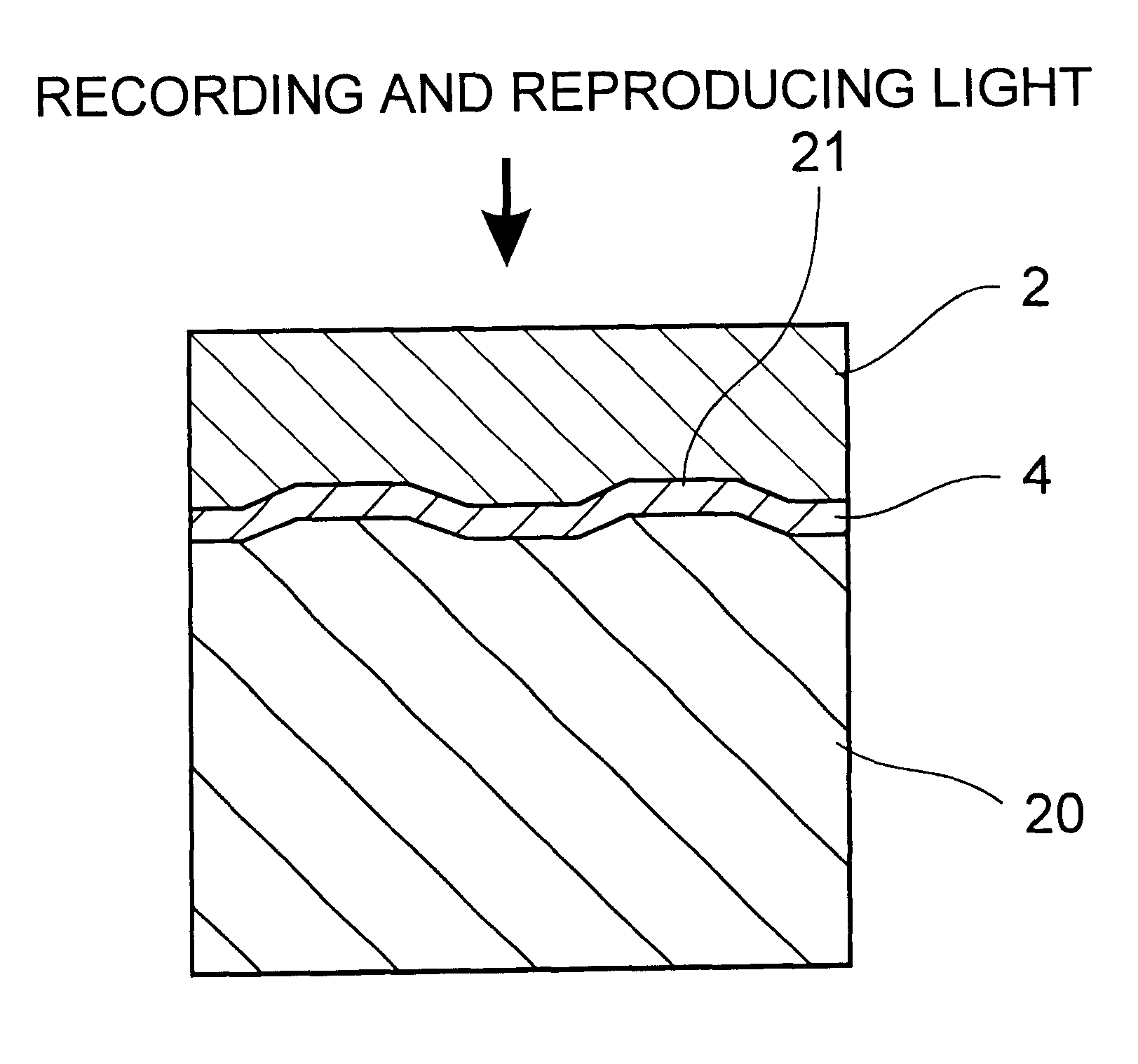
An object of the present invention is to provide an optical information medium comprising a supporting substrate, an information-recording surface provided on a surface of said supporting substrate and a light-transmitting layer provided on said information-recording surface and formed of a resin, wherein said light-transmitting layer is allowed to have a uniform thickness so that optical heterogeneity of the light-transmitting layer in its thickness direction can be reduced, and any warping of the optical information medium is prevented.

Problems solved by technology

However, it is very difficult to form the light-transmitting layer used for this structure, using resin injection molding.
When a light-transmitting layer is formed by the processes set forth in the aforesaid publications, however, a medium warping problem arises due to shrinkage upon curing of the resin forming part of the light-transmitting layer.
When the photo-curing resin is configured into a film of about 0.1 mm in thickness, it is difficult to achieve uniform curing in the thickness direction.
As a result, the light-transmitting layer lacks optical uniformity, and the reliability of the medium is likely to become low due to the presence of uncured monomers.
However, the distortion by shrinkage of the resin upon ultraviolet curing leads to another problem that the index of birefringence of the light-transmitting sheet becomes large.

Method used


Image

  • Optical information medium and its fabrication process
  • Optical information medium and its fabrication process

Examples


example 1

Read only optical disk samples shown in Table 1 were prepared through the following process steps.

Sample No. 1

By sputtering, a reflective film made of an Al alloy was formed on the surface of a disk form of supporting substrate (a polycarbonate substrate of 120 mm in diameter and 1.2 mm in thickness) having asperities defining pits for carrying information thereon, as seen from the light-transmitting layer side.

Then, a resin (having a viscosity of 92 cps at 25.degree. C.) containing an ultraviolet-curing cationic resin and a photo-polymerization initiator was coated on the surface of the reflective film by means of a dispenser, then spin-coated at 2,000 rpm for 2 seconds, and finally cured by ultraviolet irradiation. For the ultraviolet-curing cationic resin a mixture of alicyclic epoxy resins was used, and for the photopolymerization initiator an aromatic sulfonium salt was used. This cycle of dispenser coating.fwdarw.spin coating.fwdarw.curing was repeated five times in all, there...


PUM

PropertyMeasurementUnit
thicknessaaaaaaaaaa
thicknessaaaaaaaaaa
diameteraaaaaaaaaa

Abstract

An optical information medium comprises a supporting substrate, an information recording surface 4 on the supporting substrate and a light-transmitting layer of resin on the information recording surface. Recording light and / or reproducing light are incident on the information recording surface through the light-transmitting layer. The light-transmitting layer is obtained by curing a resin layer containing an ultraviolet-curing cationic resin. If the light-transmitting layer is formed by repeating the cycle of resin coating and curing or drying a plurality of times, the uniformity of thickness of the light-transmitting layer can be much more improved and the amount of warpage can be much more reduced. Repetition of the cycle of resin coating and curing or drying is also effective for resins other than the ultraviolet-curing cationic resin.

Description

BACKGROUND OF THE INVENTIONThe present invention relates to an optical information medium such as read only optical disks and optical recording disks and its fabrication process.In recent years, optical information media such as read only optical disks and optical recording disks have been required to have ever-higher recording densities and, hence, ever-higher capacities so as to record or store an enormous amount of information such as moving image information. To meet this requirement, media having such high recording densities are now under extensive and intensive research and development.According to one of approaches proposed so far to this end, recording and reproducing wavelengths are shortened while the numerical aperture (NA) of an objective in a recording and reproducing optical system is increased, thereby reducing the diameter of recording and reproducing laser beams, as typically practiced in the case of a digital versatile disk or DVD. When the recording and reproduci...

Claims


Application Information

Patent Timeline
Patent Type & Authority Patents(United States)
IPC IPC(8): G11B7/24G11B7/254G11B7/26G11B7/2534G11B7/2542
CPCG11B7/2542G11B7/26G11B7/2534Y10T428/21G11B7/256
Inventor HIRATA, HIDEKI
Owner TDK CORPARATION
Learn More