Eureka AIR delivers breakthrough ideas for toughest innovation challenges, trusted by R&D personnel around the world.

Surface mountable over-current protecting device

a protection device and surface mount technology, applied in the direction of resistor housing/enclosement/embedding, positive temperature coefficient thermistors, other domestic articles, etc., can solve the problem of not teaching about how to solve a thermal conduction problem, the connection between the ptc apparatus and the pair of conductive metal terminals is not strong enough to withstand a reflow process, and the edge fracture of the ptc apparatus

Inactive Publication Date: 2002-04-23
POLYTRONICS TECH
View PDF10 Cites 100 Cited by
  • Summary
  • Abstract
  • Description
  • Claims
  • Application Information

AI Technical Summary

Benefits of technology

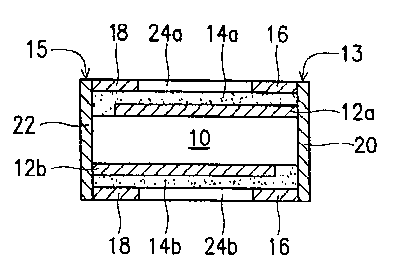
In order to achieve the above-mentioned objective, the present invention introduced a novel design and process. The present invention proposes an electrical apparatus for surface mounting, which allocates the electrode films of both planar sides of a normal thermal-sensitive resistance apparatus, such as a PTC apparatus to laminate with an outer electrode layer, and a plurality of vias electroplated with conductive material are used to connect to any plane. It is convenient to mount the apparatus according to the present invention on a printed circuit board.
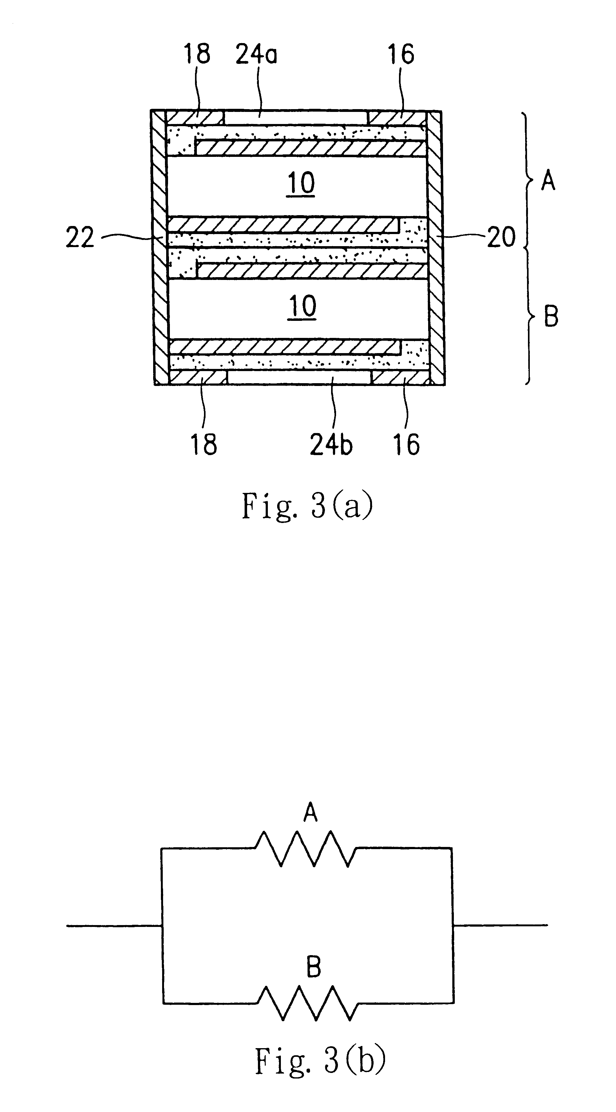
Different from prior art, the present invention teaches a novel way to construct at least a two-layer resistive apparatus by adhesion, and to eliminate the prior design shortfall that the thermal diffusion of the surface mounting resistance is sensitive to on line width on the circuit board and environments. Additional disadvantages, such as non-uniformity of stress, easy bending of PTC resistive assembly, and variation of resistance due to the difference of thermal expansion coefficients between metal foil electrodes and the conductive polymer material, can be overcome by the designing device with better dimensional stability in the X-Y axis according to the present invention. In prior designs, such as U.S. Pat. Nos. 5,831,510 and 5,852,397, each side of the electrodes must have an etching line, which results in the reduction of the effective area. The present invention only etches small area of first and second conductive components surrounding the second and first end surfaces respectively. This design could increase the effective area and reduce device impedance. The final resistance of the multi-layer apparatus formed by connecting multiple layers in parallel could be reduced, and is equal to the reciprocal of the sum of 1 / R.sub.1, 1 / R.sub.2, 1 / R.sub.3, . . . , 1 / R.sub.n, wherein R.sub.1 to R.sub.n denotes the resistance of resistive assembly layer 1 to resistive assembly layer n respectively.

Problems solved by technology

The disadvantage of the prior art is that the connection between the PTC apparatus and the pair of conductive metal terminals is not strong enough to withstand a reflow process, and usually a disconnection occurs.
As a result, fractured edges are found in the PTC apparatus.
This patent did not teach about how to resolve a thermal conduction problem by changing the structure of the PTC apparatus.
(1) The apparatus exhibits high heat transfer rate, which causes the resistance of the apparatus to be strongly affected by its environments, such as line width, line thickness and position on the printed circuit board. Therefore, the magnitude of resistance variation from normal ("untripped") state to tripped state becomes unpredictable and hard to control.
(2) Due to the difference of thermal expansion coefficients between a metal electrode and the conductive organic polymer material, the stress embedded in the PTC apparatus is not uniform. Consequently, the metal electrode is susceptible to delamination during service and thereby loses its electrical function.
(3) Each of the electrode foils on the surfaces of the upper and lower end should be separated by etching to form two sections on each of the surfaces. As a consequence, effective area is reduced.
In prior designs, such as U.S. Pat. Nos. 5,831,510 and 5,852,397, each side of the electrodes must have an etching line, which results in the reduction of the effective area.

Method used


Image

  • Surface mountable over-current protecting device
  • Surface mountable over-current protecting device
  • Surface mountable over-current protecting device

Examples


Embodiment Construction

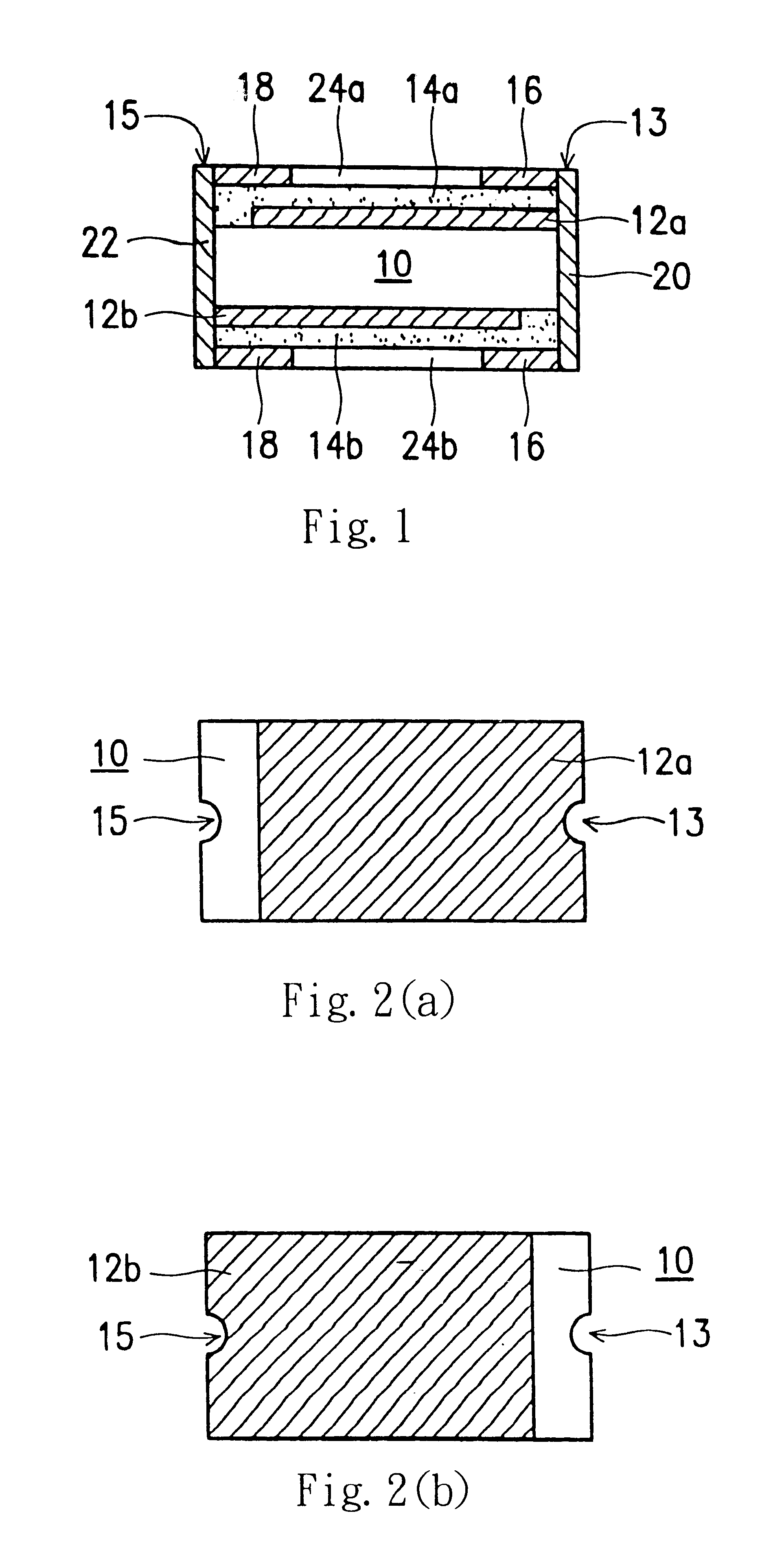
A surface mounted thermal-sensitive resistance apparatus according to a preferred embodiment of the present invention is illustrated by FIG. 1 to FIG. 3. Firstly, FIG. 1 is a side view of the electrical apparatus according to a preferred embodiment of the present invention, and the electrical apparatus shown in FIG. 1 mainly comprises a thin-board resistive component 10, first and second insulating films 14a and 14b, first and second conductive components 12a and 12b, and outer electrodes 16 and 18 coupled to the conductive films 20 and 22 respectively.

The resistive component 10 is made of a polymer material with conductive particles dispersed therein and having a characteristic of a positive or negative temperature coefficient. Polymeric materials suitable for the resistive component of the present invention comprises: polyethylene, polypropylene, polyvinyl fluoride, compound and copolymer of the materials mentioned above. The conductive particle can be a metal particle, carbon par...


PUM


Abstract

The present invention relates to a novel thermal-sensitive resistive apparatus, such as PTC and NTC, which allocates planar electrode films on the top and bottom surfaces of a prior art thermal-sensitive resistive apparatus, such as a PTC apparatus, to laminate with an outer electrode layer. A plurality of interconnection vias are electroplated with conductive material to connect to any plane. It is convenient to surface mount the apparatus of the present invention on a printed circuit board. The present invention can largely increase the dimensional stability of components and overcome the disadvantage that thermal diffusion of the prior are surface mounted resistive apparatus is affected easily by line width and environments.

Description

1. Field of the InventionThe present invention relates to a surface-mounted thermal-sensitive resistance apparatus, such as a positive-temperature-coefficient (PTC) or negative-temperature-coefficient (NTC) element, which is mainly applied to a printed circuit board (PCB) for sensing overloading current and abnormal temperature variation to protect elements on the PCB.2. Description of the Related ArtA conductive composition material made of an organic polymer, such as polyethylene, and a conductive material, such as carbon black, metal particle or metal powder, has many applications. Among the applications, the resistance variation of a non-linear PTC apparatus is the most outstanding. The characteristic of the PTC apparatuses can be used to design electronic components or electrical apparatuses for protecting circuits from damage by overheating or over-threshold current.In other words, the resistance of the PTC material is very low at normal temperatures and increases immediately ...

Claims


Application Information

Patent Timeline
IPC IPC(8): H01C7/12H01C7/04H01C7/02H01C1/032H01C1/14H01C1/02H05B3/10H05B3/22H05B3/14
CPCH01C1/032H01C1/1406H01C1/1413H01C7/027H01C7/049H01C7/12H05B3/146H05B3/22H05B3/10Y10S428/901H05B2203/013H05B2203/017H05B2203/019H05B2203/02
Inventor CHU, FU-HUAMA, YUN-CHINGWANG, DAVID SHAU-CHEW
Owner POLYTRONICS TECH
Why Eureka
Eureka Blog
Learn More