Portable solar generator

Inactive Publication Date: 2002-05-28
BENN WILLIAM M +1
View PDF4 Cites 325 Cited by
  • Summary
  • Abstract
  • Description
  • Claims
  • Application Information

AI Technical Summary

Benefits of technology

The compact size, flexibility, mobility and modularity of the present invention provides an easy to install and maintain device. The present invention is a significant benefit to the community. It provides an independent distributed power source that can eliminate power blackouts or brownouts for users.Although the above-preferred embodiments have been described with specificity, persons skilled in this art will recognize that many changes to the specific embodiments disclosed above could be made without departing from the spirit of the invention. For example, although the second preferred embodiment discusses connecting the main PV modular platform to two auxiliary PV modular platforms, it is also possible to connect it to just one auxiliary PV modular platforms or more than two auxiliary PV modular platforms. Also, it is possible to have other devices capable of generating electricity connected to a main PV modular platform , such as a windmill or a fuel-burning generator. Also, although FIG. 8 showed PV panels 10 wired in parallel, they could also be wired in series. Also the batteries 26 could be wired in series or parallel depending on the application of the system. Also, although the above described embodiments showed lead acid batteries 26 charged by the present invention, the present invention could be used to charge fuel cells. Therefore, the attached claims and their legal equivalents should determine the scope of the invention.

Problems solved by technology

However, the cart disclosed by Azzam is inadequate for effectively supplying enough energy to satisfy the needs of a typical residence.

Method used


Image

  • Portable solar generator
  • Portable solar generator
  • Portable solar generator

Examples


second preferred embodiment

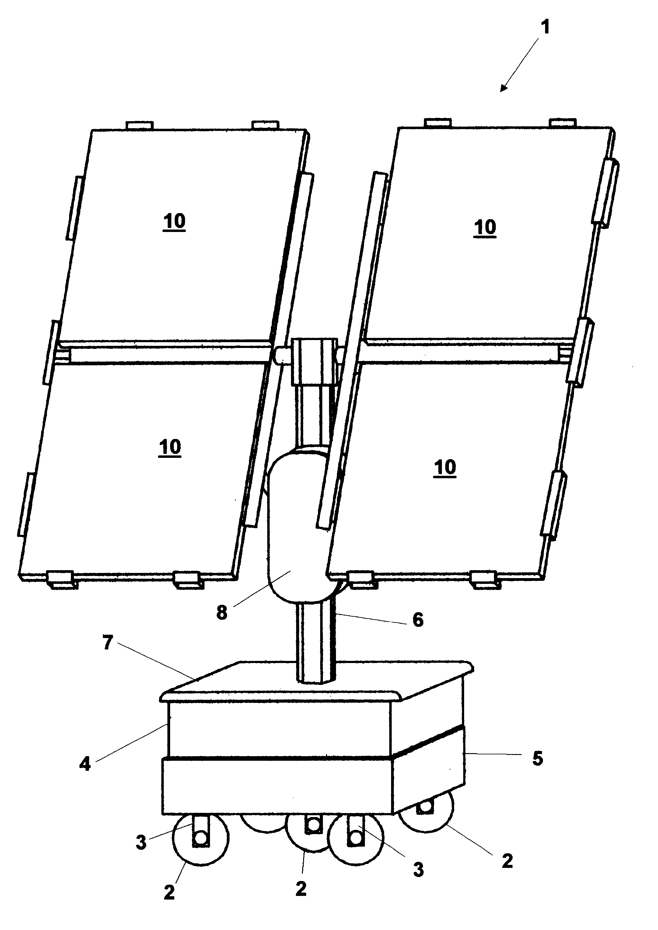
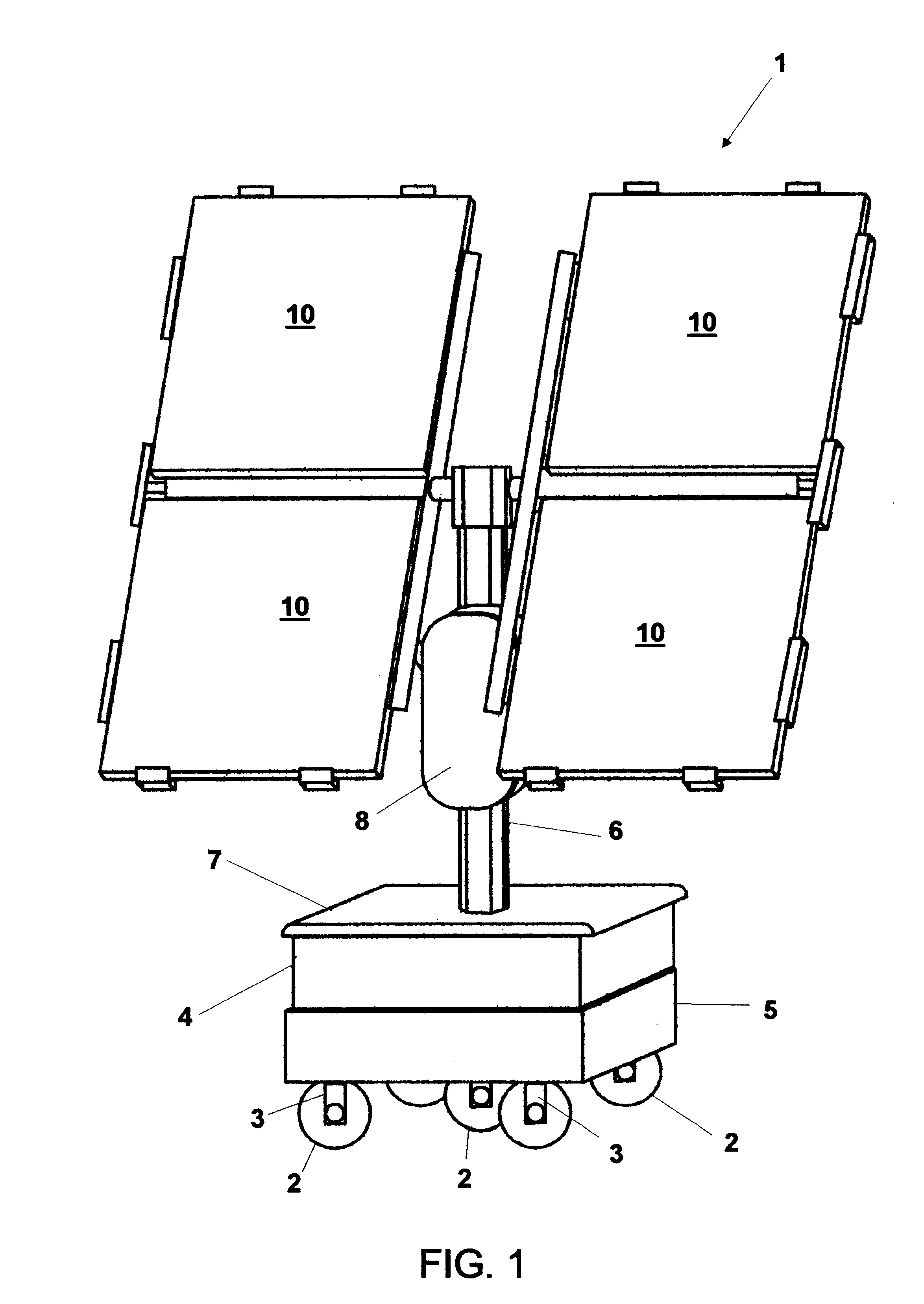
In the first preferred embodiment, PV modular platform was shown as a stand alone platform. In the second preferred embodiment, two auxiliary PV modular platforms are added to a main PV modular platform 1. The auxiliary PV modular platform is similar in design to PV modular platform 1 described above with the exception that the auxiliary PV modular platform preferably does not contain an inverter. The inverter is unnecessary because the DC current from the auxiliary unit will feed directly into the main PV modular platform 1 at via switch 112 (FIG. 8).

By connecting two auxiliary PV modular platforms to PV modular platform 1, the entire system can provide approximately 1.2 kilowatts. This is enough to power a house. It is estimated that the total purchase price for two auxiliary PV modular platforms and a main PV modular platform is approximately $11,000. If the current monthly electric bill for a residential electricity user is $300 / month, it will take slightly more than three years...


PUM


Abstract

A portable PV modular solar generator. A plurality of wheels are attached to the bottom of a rechargeable battery container. At least one rechargeable battery is contained inside the rechargeable battery container. A power conditioning panel is connected to the rechargeable battery container. At least one photovoltaic panel is pivotally connected. In a preferred embodiment, the rechargeable battery container is a waterproof battery enclosure having a knife switch connection. A mast having a rotation bar is supported by the waterproof battery enclosure. At least one solar panel support brace for supporting the photovoltaic panel is attached to the rotation bar. The power conditioning panel is waterproof, is attached to the mast and has a door. When the door is opened, at least one safety switch is opened, breaking an electric circuit. The waterproof power conditioning panel has a charge controller and an inverter. The charge controller is electrically connected to at least one rechargeable battery and at least one photovoltaic panel, and is capable or receiving auxiliary power inputs.

Description

The present invention relates to solar electric generators, and in particular, to portable solar electric generators.In recent years, the cost of generating electricity has increased dramatically. In California, the monthly electric bill for many consumers has more than doubled in the past year. Rolling blackouts, a condition in which geographical sections of the community are alternately cut-off from receiving electricity during an electrical shortage crisis, are becoming increasingly commonplace with more predicted for the summer of 2001. As our planet's natural resources are depleted and as population increases, the importance of effectively harnessing alternative methods of generating electricity has increased.Solar EnergyPhotovoltaic panels (also called solar panels) are well known and are used to generate electricity from sunlight. Sunlight is "free" and so the cost of electricity generated by a photovoltaic panel is extremely low. However, solar energy is not widely used to g...

Claims


Application Information

Patent Timeline
IPC IPC(8): H02J7/35H01M10/46H01M10/42H01M2/10H01L31/042F24J2/36F24J2/54F24S50/20H01M50/204H01M50/24H01M50/251H01M50/264
CPCF24J2/36H02S30/20F24J2/542H01M10/465H02J7/355F24J2/38H02S20/00F24J2002/5489H01M2/1016Y02B10/14Y02B10/20Y02E10/47Y02E10/50F24J2002/0084F24J2/523H02S20/30H02S10/40F24S2030/17F24S20/50F24S2020/16F24S50/20F24S25/10F24S30/452H02J7/35Y02B10/10Y02E10/56Y02E60/10H01M50/204H01M50/264H01M50/251H01M50/24
Inventor BENN, WILLIAM M.BENN, JOHN T.
Owner BENN WILLIAM M
Why Eureka
Try Eureka