
Controlling superplastic forming with gas mass flow meter

Inactive Publication Date: 2001-10-23
MCDONNELL DOUGLAS
View PDF12 Cites 7 Cited by
  • Summary
  • Abstract
  • Description
  • Claims
  • Application Information

AI Technical Summary

Benefits of technology

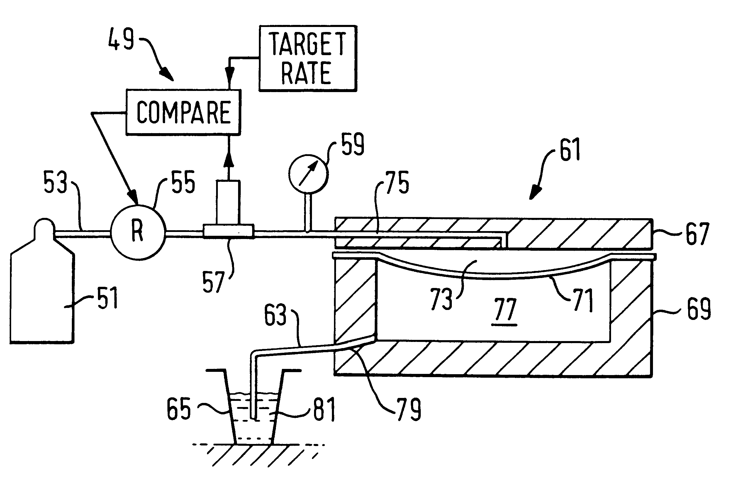
Given the shape and volume of an object to be superplastically formed from a metal sheet, the forming time is estimated by empirical analysis. The rate of gas mass flow into a forming cavity required to reliably and efficiently form the object is then determined using either a nomograph composed of four interrelated graphs, or a single graph which requires the input of fewer variables than the nomograph. Although the single graph is less precise than the nomograph, it will provide accuracy sufficient for many applications.

Problems solved by technology

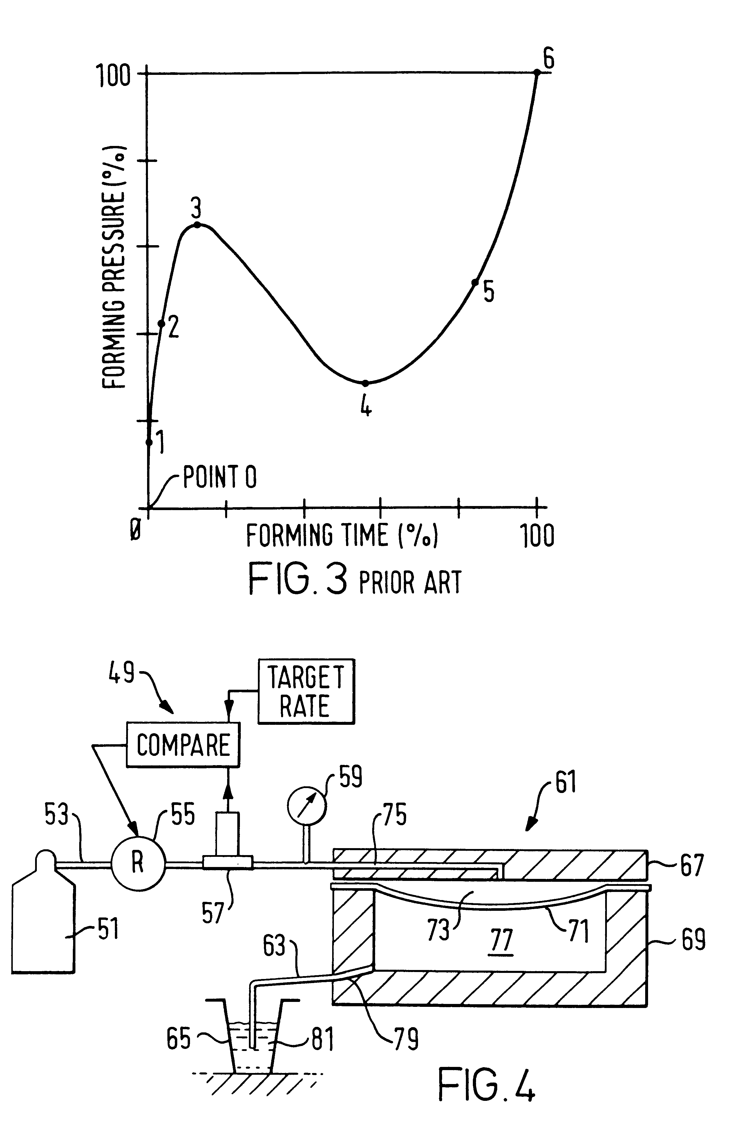
As can be seen therein, the calculations necessary to derive the forming pressure versus time graph are complex and very time consuming, even for the simple geometry of a rectangular pan.
The problem inherent to the foregoing approaches is that any mathematical model used to obtain a graph of forming pressure versus time is only an approximation because the assumed value for the strain rate used in the model cannot be determined with any degree of certainty and, furthermore, the strain rate is assumed to remain constant whereas, in fact, it varies throughout the forming cycle as well as spatially across the forming sheet.
The empirical value for m is thus an approximation for the entire forming process, and the reliability of the pressure versus time graph will suffer as m varies due to the aforementioned factors.
Their accuracy is also adversely affected by slippage of the sheet after it comes into contact with the interior surface of the die cavity.
In addition, mathematical models fail to account for differences in superplasticity that inevitably occur among different sheets of the same alloy, caused by innate variations in the production process.
In summary, the assumptions and approximations necessary to the mathematical analysis for deriving the forming pressure as a function of time, introduce errors which adversely affect the reliability of the relationship, especially as the geometry of the object becomes more complex.
This inaccuracy causes a difference between the actual position of the forming sheet and its predicted position.
The forming pressure versus time graph does not correct for such deviations, with the result that an inappropriate forming pressure may be applied.
Rupture may be the result.
Both of the foregoing approaches require breaching the die cavity, and thus add mechanical complexity and expense to the forming die.
This will result in the area of the sheet in contact with the sensor being prevented from forming normally, thus affecting the strain rate and causing a discontinuity in material thickness in the formed object between the area that was in contact with the sensor and the adjacent area.
Such a special forming die would clearly be more expensive to fabricate than a conventional forming die.
A further drawback is that the sheet must be continually observed by the operator during the forming process, and therefore the use of the described apparatus does not lend itself to automation and the attendant savings in production cost.
Although this apparatus is useful for testing the forming of cylindrical shapes, the foregoing analyses can be complex.

Method used


Image

  • Controlling superplastic forming with gas mass flow meter
  • Controlling superplastic forming with gas mass flow meter
  • Controlling superplastic forming with gas mass flow meter

Examples


Embodiment Construction

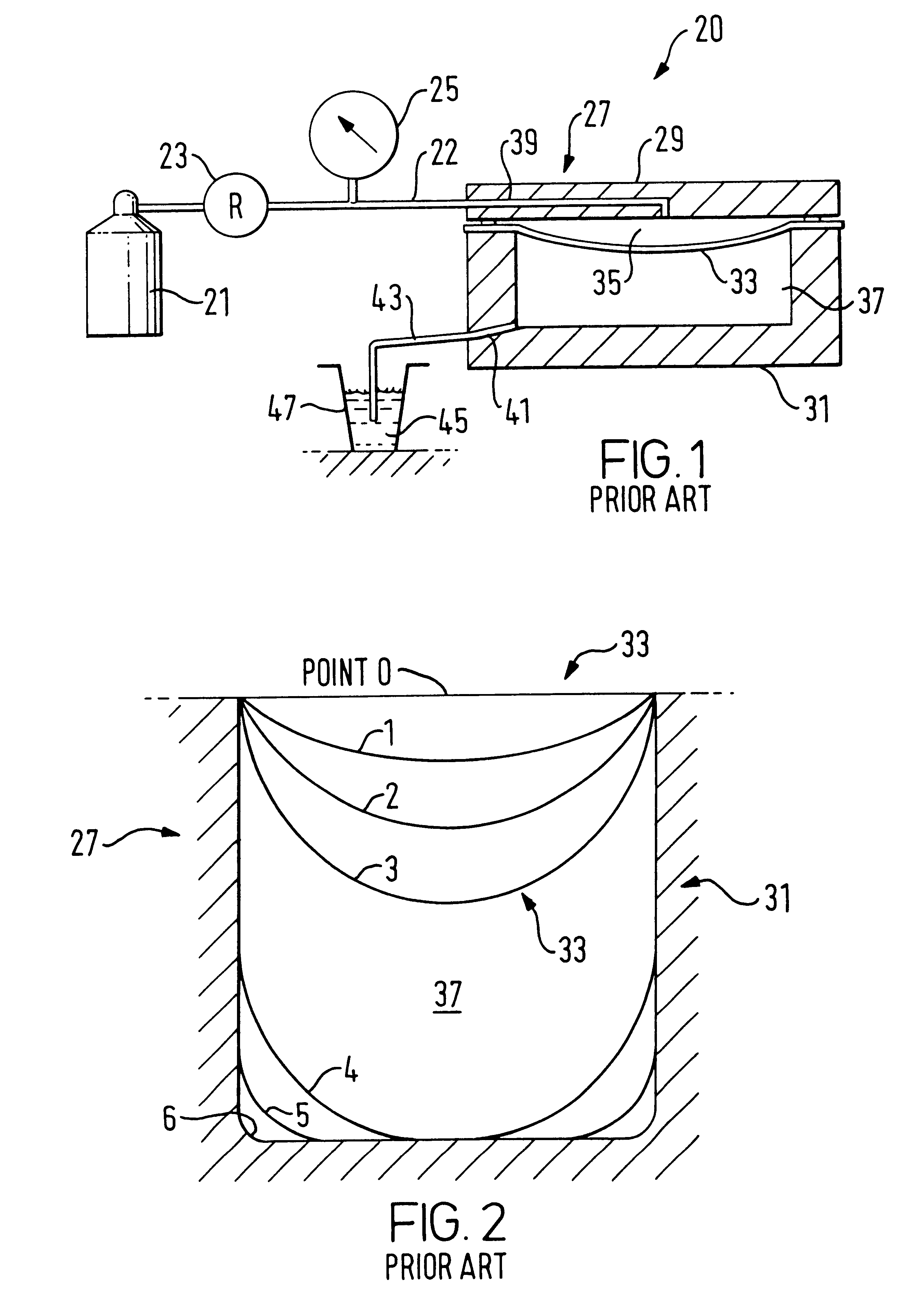
FIG. 1 is a schematic of a simple prior art superplastic forming apparatus 20, which controls superplastic forming by regulating the forming pressure as a function of time. Apparatus 20 includes gas bottle 21, gas input line 22, pressure regulator 23, pressure gage 25, and forming die 27. Bottle 21 contains a pressurized inert gas, typically argon gas. This is known as the forming gas. Input line 22 fluidly communicates bottle 21, pressure regulator 23, pressure gage 25, and forming die 27. Forming die 27 is comprised of lid 29 and bottom section 31.

Metal sheet 33 is rigidly positioned in forming die 27 by having its periphery tightly compressed in between lid 29 and bottom section 31. Volume 35 is contained by sheet 33 and lid 29. Input port 39 is a passageway through lid 29 providing for fluid communication between input line 22 and volume 35. Bottle 21 thus fluidly communicates with volume 35.

Forming cavity 37 is a volume enclosed by bottom section 31 and sheet 33. Volume 35 and ...


PUM

PropertyMeasurementUnit
Pressureaaaaaaaaaa
Pressureaaaaaaaaaa
Pressureaaaaaaaaaa

Abstract

The forming time necessary to superplastically form an object from a metal sheet is estimated by empirical analysis. The required rate of gas mass flow into a forming cavity is then determined using either a nomograph composed of four interrelated graphs, or a single graph which requires the input of fewer variables than the nomograph. The present invention may also be used to form cells of multiple sheet panels from a stack of sheets. In the latter application, forming time necessary to complete forming of the cells from an interim point where the core sheet forming pressure and the die temperature are increased from interim levels to their final values is estimated by empirical analysis. A nomograph or single graph of the present invention then determines the gas mass flow rate necessary to safely and efficiently complete forming of the cells from the foregoing interim point. In both of the foregoing embodiments, the required gas mass flow rate, which is a target value, is maintained by regulating the forming pressure until the final forming pressure is reached.

Description

FIELD OF THE INVENTIONThis invention relates to the field of metal forming and, more particularly to the forming of objects from alloys which exhibit superplastic characteristics, by regulating the forming pressure during the superplastic forming process so that the forming gas flows into the forming die at a predetermined mass flow rate.BACKGROUND OF THE INVENTIONWhen heated to a particular temperature range, certain alloys arc capable of undergoing enorinous plastic elongation, or strain, with uniform thinning throughout the full area of a metal sheet or blank. This characteristic, known as superplasticity. is used to form objects from such alloys by placing a metal sheet in a forming die containing a die cavity, heating the sheet to the desired temperature, and then applying a pressure differential to the respective sides of the sheet for a period of time. The pressure differential, known as the forming pressure, is obtained by introducing a pressurized inert gas into the sealed ...

Claims


Application Information

Patent Timeline
IPC IPC(8): B21D26/02B21D26/00B21D26/055
CPCB21D26/055Y10T29/49805Y10S72/709
Inventor YASUI, KEN K.
Owner MCDONNELL DOUGLAS
Learn More