
Reversible electrochemical mirror (REM) state monitoring

a state monitoring and electrochemical mirror technology, applied in non-linear optics, instruments, optics, etc., can solve the problems of increasing air conditioning requirements and costs, unfavorable environment, and only partially effective approaches

Inactive Publication Date: 2001-10-09
TELEDYNE SCI & IMAGING
View PDF1 Cites 189 Cited by
  • Summary
  • Abstract
  • Description
  • Claims
  • Application Information

AI Technical Summary

Problems solved by technology

Sunlight transmitted through windows in buildings and transportation vehicles can generate heat (via the greenhouse effect) that creates an uncomfortable environment and increases air conditioning requirements and costs.
These approaches are only partially effective, since the window itself is heated and because these devices, such as electrochromic devices, are relatively expensive and exhibit limited durability and cycle life.
Certain liquid crystal-based window systems switch between transmissive and opaque / scattering states, but these systems require substantial voltages to maintain the transparent state.
Bright light from headlamps on following vehicles reflected in automobile rear and side view mirrors is annoying to drivers and creates a safety hazard by impairing driver vision.
Such devices do not provide close control over the amount of reflected light, and are expensive to fabricate since a very constant inter-electrode spacing is required to provide uniform dimming.
In early attempts to exploit reversible electrodeposition of a metal for light modulation, the deposits obtained on transparent substrates presented a rough and black, gray, or sometimes colored appearance (typical of finely-divided metals) and exhibited poor reflectivity and high light absorbance, especially when thick.
Warszawski (U.S. Pat. No. 5,056,899), which is concerned with displays, teaches that reversible metal electrodeposition is most appropriate for display applications, since significant disadvantages for transmission devices were given (e.g., the possibility of metal deposition at the counter electrode).
Such teachings imply that the application of reversible metal deposition to smart windows must involve light absorption by the finely divided electrodeposited metal, which would result in heating of the device itself and thus the space inside.
The low reflectance of this type of deposit would not be appropriate for adjustable mirror applications.
These authors also utilized a counter electrode reaction other than metal electrodeposition / dissolution, and also never obtained a mirror deposit.
Thus, Ziegler et al. provide no teachings relevant to the effect of electrolyte composition on the deposition / dissolution rate and quality of mirror electrodeposits.
Such electrolytes, however, have much more limited temperature and voltage operating ranges compared with organic-based electrolytes with high boiling solvents.
Unfortunately, such additives are typically destroyed during the electrodeposition process, greatly limiting cycle life.
Furthermore, this approach fails to produce highly-reflective mirror-like deposits that are required for adjustable mirror applications and provide the superior heat rejection needed for smart windows.
However, the described electrolytic formulation fails to provide the inherent stability, high quality deposits, good erasure and long cycle life needed for practical applications.
Since no metal electrodeposition occurs in electrochromic devices, however, the grid in this case is used to provide a transparent electrode, not to maintain transparency by localizing metal deposition.
A significant problem with adjustable mirrors of the type suitable for automotive applications, including both REM and electrochromic mirrors, is that simple means for monitoring the reflectance of such devices are not available.
Such sensors are not only expensive but are also aesthetically undesirable, increase the bulkiness of the device, and typically monitor only a small area while blocking a portion of the mirror itself.
Similar difficulties exist for variable transmission devices as well.
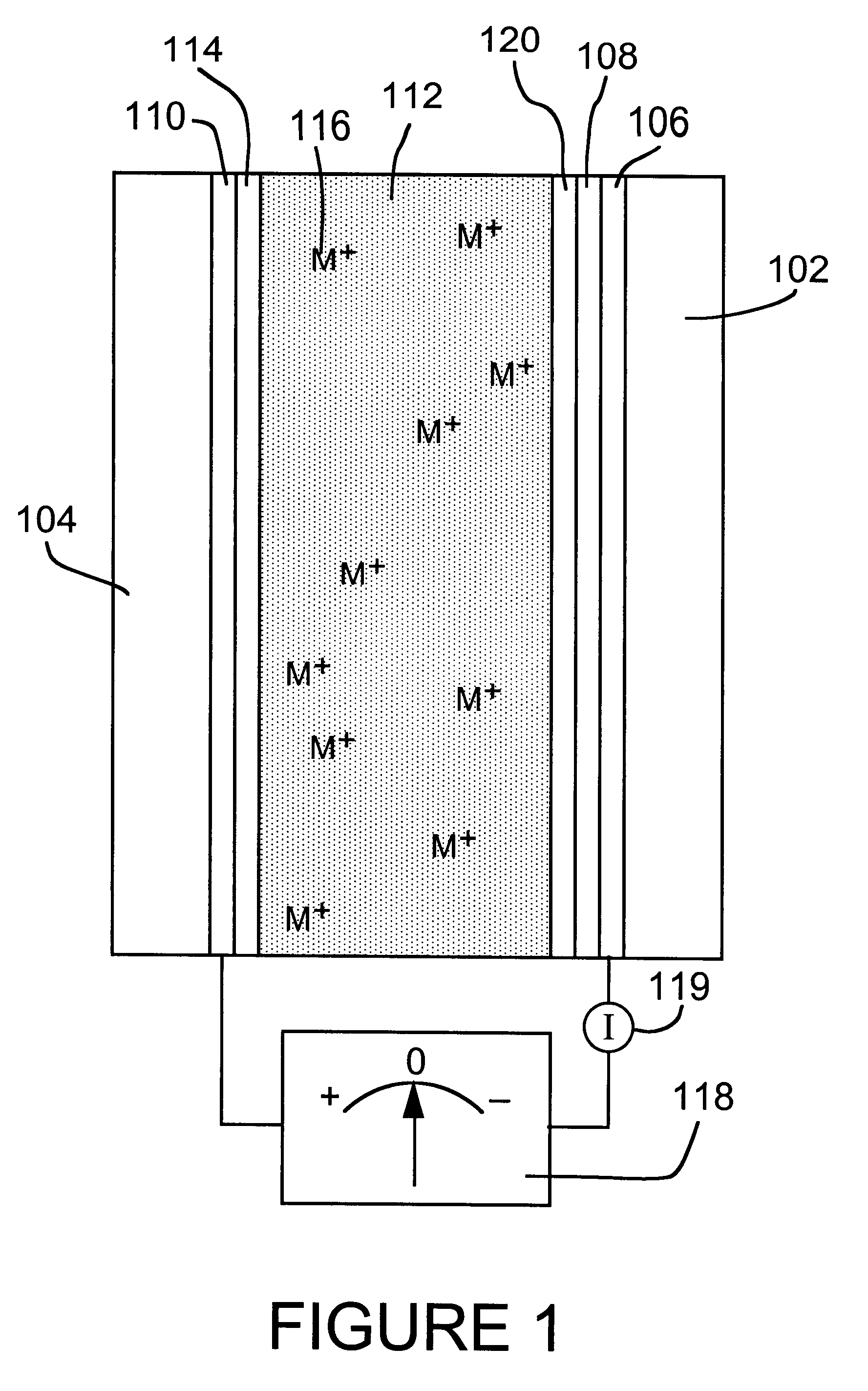
However, as the mirror was subjected to multiple cycles in which complete erasure of the mirror metal did not occur, measurement imprecision and minor efficiency imbalances between the metal electrodeposition and dissolution reactions would introduce cumulative errors in the calculated thickness and associated reflectance.
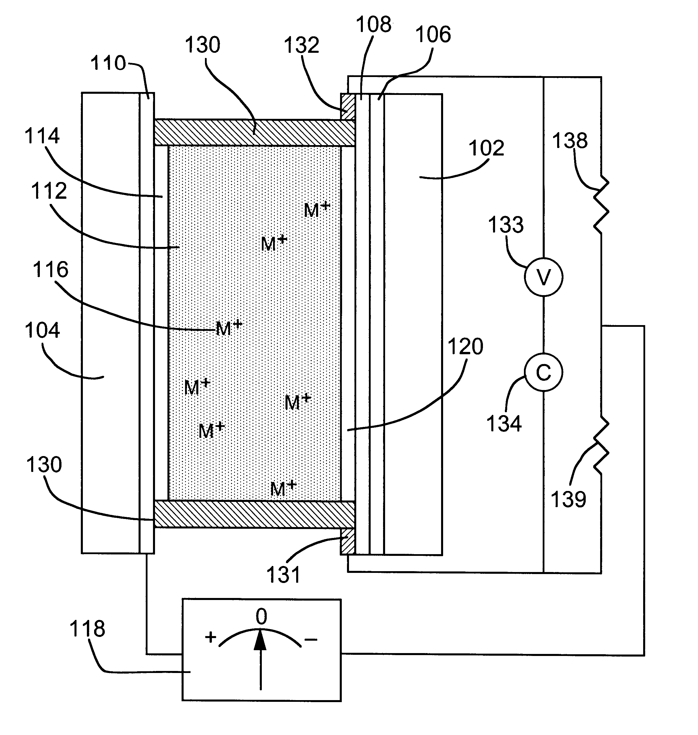
These errors could be mitigated by periodic full erasure of mirror metal layer 120 from mirror electrode 106 to establish a new starting point for the charge integration, but this would be impractical at high cycle rates and the necessity of such periodic erasure would be unacceptable for many applications.
In addition, the equipment required for accurate coulometric tracking is relatively expensive.
In addition, contacts exposed to the electrolyte would have to be sufficiently corrosion-resistant to avoid degradation under anodic voltages used for mirror state switching, which would require more expensive materials or coatings while providing no advantage.
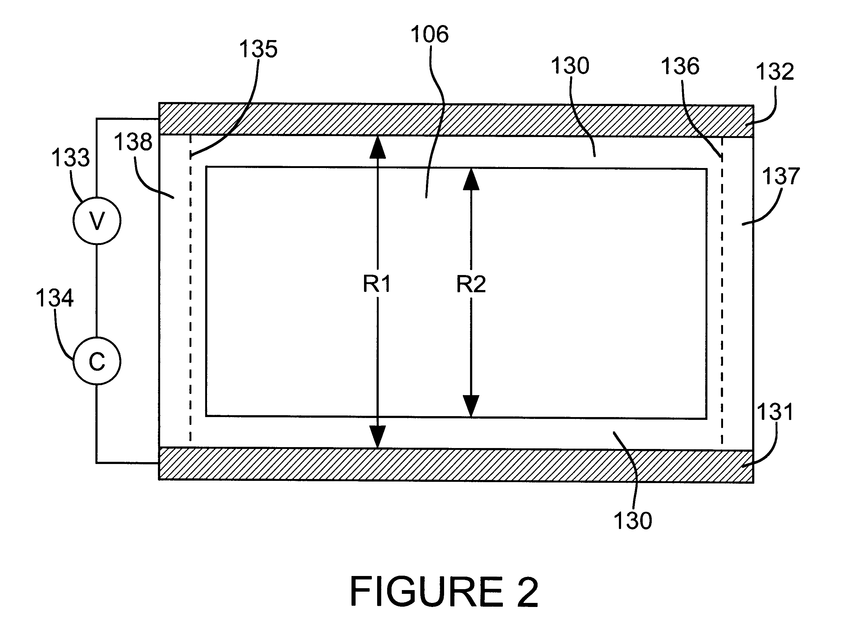
In principle, the sheet resistance can be calculated as a function of the thickness of the mirror metal deposit but the calculation is complicated by geometric considerations.
In this case, however, the extra mirror electrode material represents an additional current path that can cause non-uniform current distribution for both the resistance measurement and mirror state switching.
Solubility considerations may limit the acceptable combinations of mirror metal salts and halide / pseudohalide compounds.

Method used


Image

  • Reversible electrochemical mirror (REM) state monitoring
  • Reversible electrochemical mirror (REM) state monitoring
  • Reversible electrochemical mirror (REM) state monitoring

Examples


Embodiment Construction

An adjustable reflectivity REM device having a viewing area of approximately 6.1.times.8.9 cm was constructed using a mirror working electrode comprised of a 15 .ANG. sputtered platinum nucleation layer on a 10-ohm / square ITO film on a glass substrate (10 cm square). The counter electrode was 60 .ANG. sputtered Pt on 10 ohm / square ITO on a glass substrate (10 cm square), which had been electroplated with about 1 .mu.m of silver from a commercial cyanide bath (Technisilver 2E, Technic Co.) and annealed at 200.degree. C. for 30 minutes in an inert atmosphere (to improve adhesion) prior to cell assembly. A bare Pt / ITO border was left around the plated silver (via masking with plater's tape) to permit formation of a good seal with acrylic adhesive tape (VHB #4910, 3M Company), which also overlapped the plated silver to protect its edges. This acrylic tape (about 5 mm wide) served as both the electrode spacer (1 mm) and primary sealant and was placed inside the perimeter of glass panes s...


PUM


Abstract

Reversible electrochemical mirror (REM) devices typically comprise a conductive oxide mirror electrode that is substantially transparent to radiation of some wavelengths, a counter electrode that may also be substantially transparent, and an electrolyte that contains ions of an electrodepositable metal. A voltage applied between the two electrodes causes electrodeposition of a mirror deposit on the mirror electrode and dissolution of the mirror deposit on the counter electrode, and these processes are reversed when the polarity of the applied voltage is changed. Such REM devices provide precise control over the reflection and transmission of radiation and can be used for a variety of applications, including smart windows and automatically adjusting automotive mirrors. According to the present invention, measurements of the sheet resistance of the mirror electrode in a REM device are correlated with the thickness of electrodeposited mirror metal and can be used to monitor the reflectance of the device. Sheet resistance measurements can be performed while the mirror state of the device is being switched if adequate isolation between the measurement and switching circuits is provided. This can be accomplished by use of external resistors or more sophisticated circuitry, or by taking advantage of the relatively high sheet resistance of the mirror electrode itself. Monitoring the reflectance of REM devices according to this invention provides significant cost and performance advantages.

Description

1. Field of the InventionThis invention is concerned with devices, such as mirrors and windows, having controllable reflectivity.2. Description of the Related ArtSunlight transmitted through windows in buildings and transportation vehicles can generate heat (via the greenhouse effect) that creates an uncomfortable environment and increases air conditioning requirements and costs. Current approaches to providing "smart windows" with adjustable transmission for use in various sunlight conditions involve the use of light absorbing materials. These approaches are only partially effective, since the window itself is heated and because these devices, such as electrochromic devices, are relatively expensive and exhibit limited durability and cycle life. Certain liquid crystal-based window systems switch between transmissive and opaque / scattering states, but these systems require substantial voltages to maintain the transparent state. There is an important need for an inexpensive, durable l...

Claims


Application Information

Patent Timeline
IPC IPC(8): G02F1/01G02F1/15G02F1/163G02F1/1506
CPCG02F1/1506G02F1/163G02F1/1525
Inventor TENCH, D. MORGAN
Owner TELEDYNE SCI & IMAGING
Learn More