
Mooring assembly for mooring a body, floating on a water mass

a technology for mooring assemblies and water masses, which is applied in the direction of mooring equipment, waterborne vessels, special-purpose vessels, etc., can solve the problems of cumbersome mooring respetively and the handling of this arm during the mooring

Inactive Publication Date: 2001-06-12
BLUEWATER TERMINAL SYST
View PDF3 Cites 18 Cited by
  • Summary
  • Abstract
  • Description
  • Claims
  • Application Information

AI Technical Summary

Benefits of technology

As a result of the measures according to the invention the rigid arm can be considerably simpler and lighter because this rigid arm must now only take up pulling forces and no bending stresses; the fact that the weight is transferred from the rigid arm to the connecting element in no way deteriorates the operation of the mooring system as such.

Problems solved by technology

This has as a drawback that the structure of this arm must be designed accordingly and in particular must be able to transfer the vertical forces, exerted thereon by the weight, to the pivot point between the rigid arm and the, at rest vertical, rigid connecting element, while the presence of the weight on or at the rigid arm has as a result that handling of this arm during the mooring and the loosening of the mooring respetively is cumbersome because, when the mooring installation is not in use, the lack of special supporting provisions will have as a result that the arm will disappear to below the water surface.

Method used


Image

  • Mooring assembly for mooring a body, floating on a water mass
  • Mooring assembly for mooring a body, floating on a water mass
  • Mooring assembly for mooring a body, floating on a water mass

Examples


Embodiment Construction

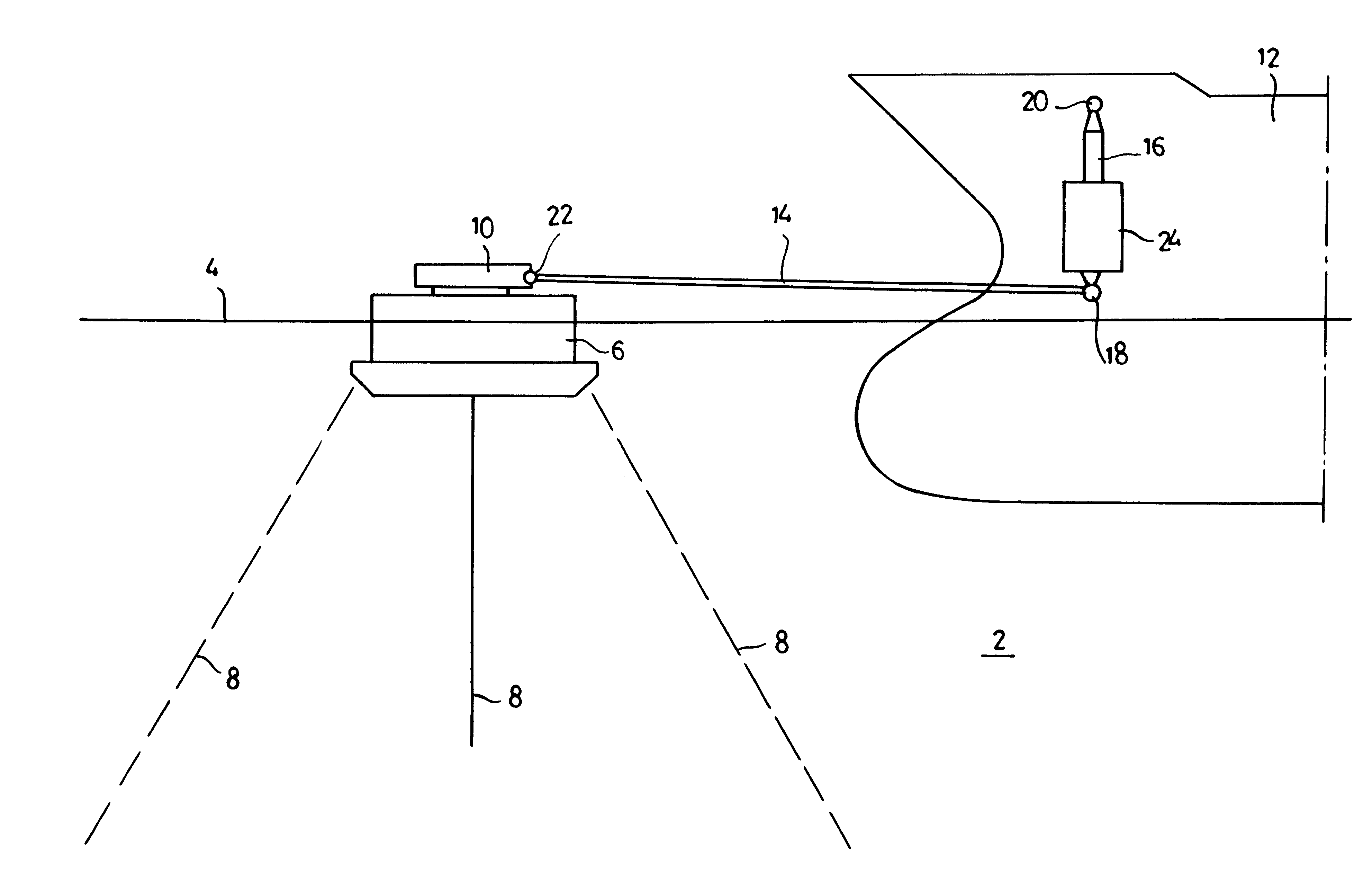
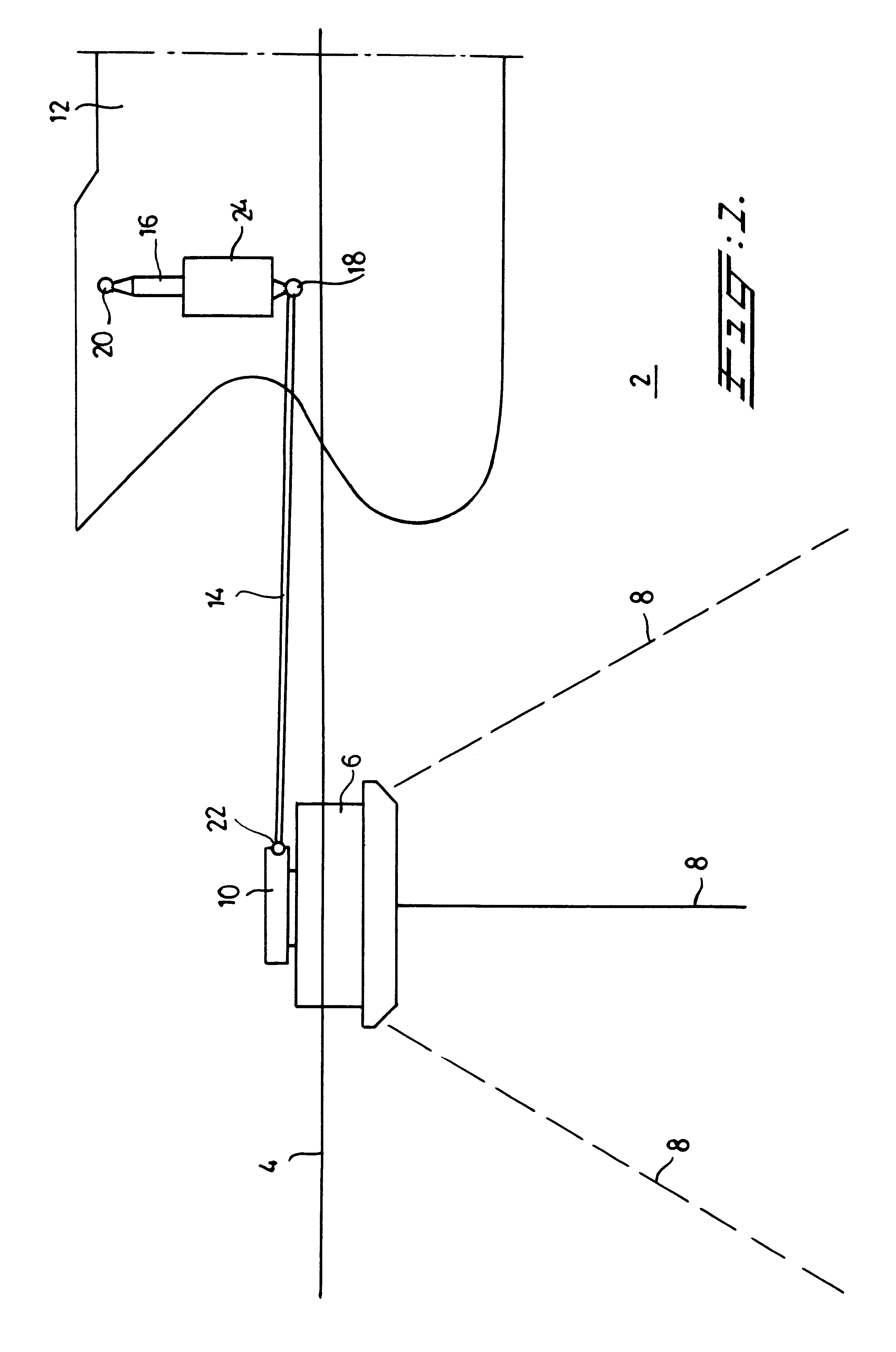
In FIG. 1 reference numeral 2 denotes a water mass; the surface thereof is denoted with reference numeral 4.

On this water mass 2 floats a mooring buoy 6, connecting to the bottom by means of anchor chains 8; the buoy 6 carries the usual turn table 10.

The figure also shows a tanker 12 floating on the water mass and anchored to the buoy 6 by means of the combination of at least one, rigid, in this case horizontal arm 14 and a vertical connecting element 16. Arm 14 and connecting element 16 are interconnected in the first pivot point 18. The connecting element 16 is connected to the tanker 12 in a second pivot point 20 and the arm 14 is connected to the turntable 10, and therewith to the buoy 6, in a third pivot point 22. When there is sufficient possibility for the buoy to "tilt" this third pivot point can be omitted.

According to the invention the connecting element 16 carries a weight 24; this can be a separate structural part fixed to the connecting element 16 or can be integrated i...


PUM


Abstract

Starting from a mooring assembly with a fixed mooring point and the combination of at least one rigid arm which, in the moored position, lies above the water surface, a rigid connecting element connected by means of a pivot point therewith and being essentially vertical at rest, and a weight, connected to the assembly and producing at movements of the floating body to and from the mooring point resetting forces acting upon this body in that the ends of the rigid arm and the connecting element respectively, opposite the first pivot point, are connected either with the mooring point on the one hand and the floating body on the other hand or with the floating body on the one hand and the mooring point on the other hand, the invention proposes that the weight is connected to the rigid connecting element. As a result the structure of the rigid arm can be simpler and the assembly will be easier to use.

Description

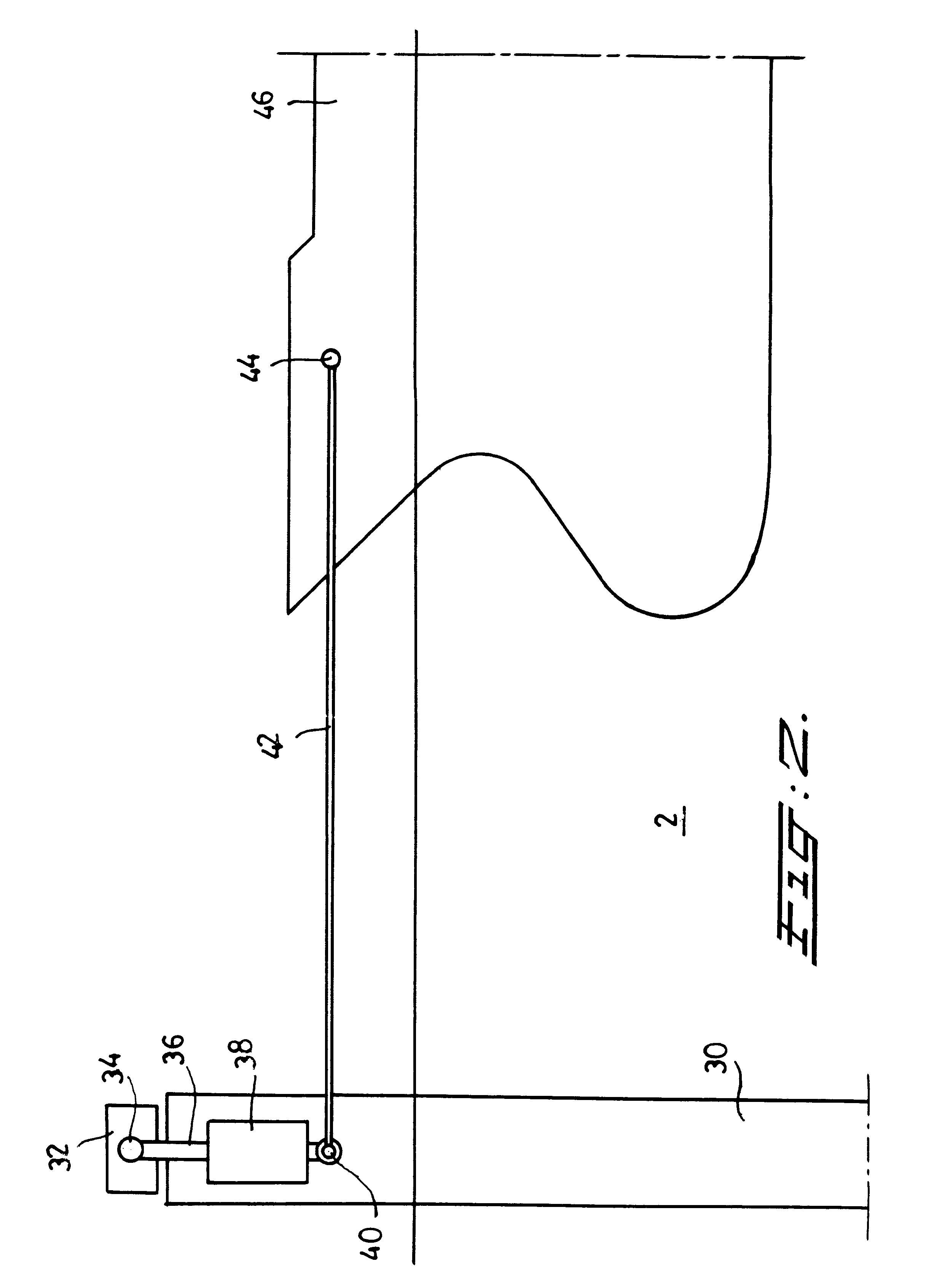
The invention relates to an assembly for mooring a body, floating on a water mass, to a mooring point--such as a floating buoy, a mooring tower, a quay or another floating body, comprising the combination of at least one rigid arm which, in the moored position, lies above the water surface, a rigid connecting element connected therewith by means of a pivot point and being at rest essentially vertical, and a weight, connected to the assembly and producing, during movements of the floating body to and from the mooring point, resetting forces acting upon this floating body because the ends of the rigid arm and the connecting element respectively, which are opposite the first pivot point, are connected either to the mooring point on the one hand and the floating body on the other hand, or to the floating body on the one hand and the mooring point on the other hand.DESCRIPTION OF THE PRIOR ARTSuch an assembly is known in itself from EP 0 096 445 B1. According to this patent publication t...

Claims


Application Information

Patent Timeline
Patent Type & Authority Patents(United States)
IPC IPC(8): B63B22/00B63B22/02E02B3/24E02B3/20
CPCB63B22/02E02B3/24B63B22/025B63B2021/002
Inventor DE BAAN, JACOB
Owner BLUEWATER TERMINAL SYST
Learn More