Decontamination apparatus

Inactive Publication Date: 2001-05-29
SEP TECH
View PDF20 Cites 8 Cited by
  • Summary
  • Abstract
  • Description
  • Claims
  • Application Information

AI Technical Summary

Benefits of technology

It is also an object of the invention to provide a pulp decontaminating apparatus that has an improved configuration for removing heavy contaminates.
Therefore, the invention provides a method for decontaminating paper pulp by inserting into a contaminated pulp stream a carrier particle having the ability to facilitate removal of contaminants from the pulp stream. An advantage of this system is to provide a method for separating small contaminates that may not be removed as efficiently from the pulp stream using traditional cleaning methods or the decontamination chamber described herein.

Problems solved by technology

Waste paper materials present a challenge to provide an economically feasible means of recycling which yields an acceptable paper product.
Second, heavy materials, such as rocks and metal pieces, are typically removed with increased effort by screen filters or traps.
Finally, light weight contaminates, such as plastics, styrofoam, wood, adhesives and entrained air, can be the most difficult to remove.
Pulp fiber screening technology has practical limits defined by screen pore size and hydraulic pressure.
However, the high degree of screening currently required to produce acceptable quality paper results in energy inefficiencies.
The removal of light weight contaminates, such as foldable bits of plastic sheeting, are especially problematic to remove by conventional screening techniques.
Prior art collection traps for light weight contaminates are also unsatisfactory.
Furthermore, this system requires an undesirable number of moving parts, which increases the likelihood of machine failure.
Traps for heavy contaminates in the prior art are also inadequate.
Again, this requires unnecessary machinery and produces circulatory agitation, which prevents both light and heavy contaminates from efficiently separating.
Furthermore, such prior art devices do not permit a continuously adjustable range of decontamination depending upon the quality of the paper product desired.
Prior art pulp decontaminators are also incapable of processing sufficiently large amounts of pulp to create an economy of scale.
Despite the apparent need for such pulp processing alternatives, there have been none which satisfactorily provide these desirable qualities.

Method used


Image

  • Decontamination apparatus
  • Decontamination apparatus
  • Decontamination apparatus

Examples


Embodiment Construction

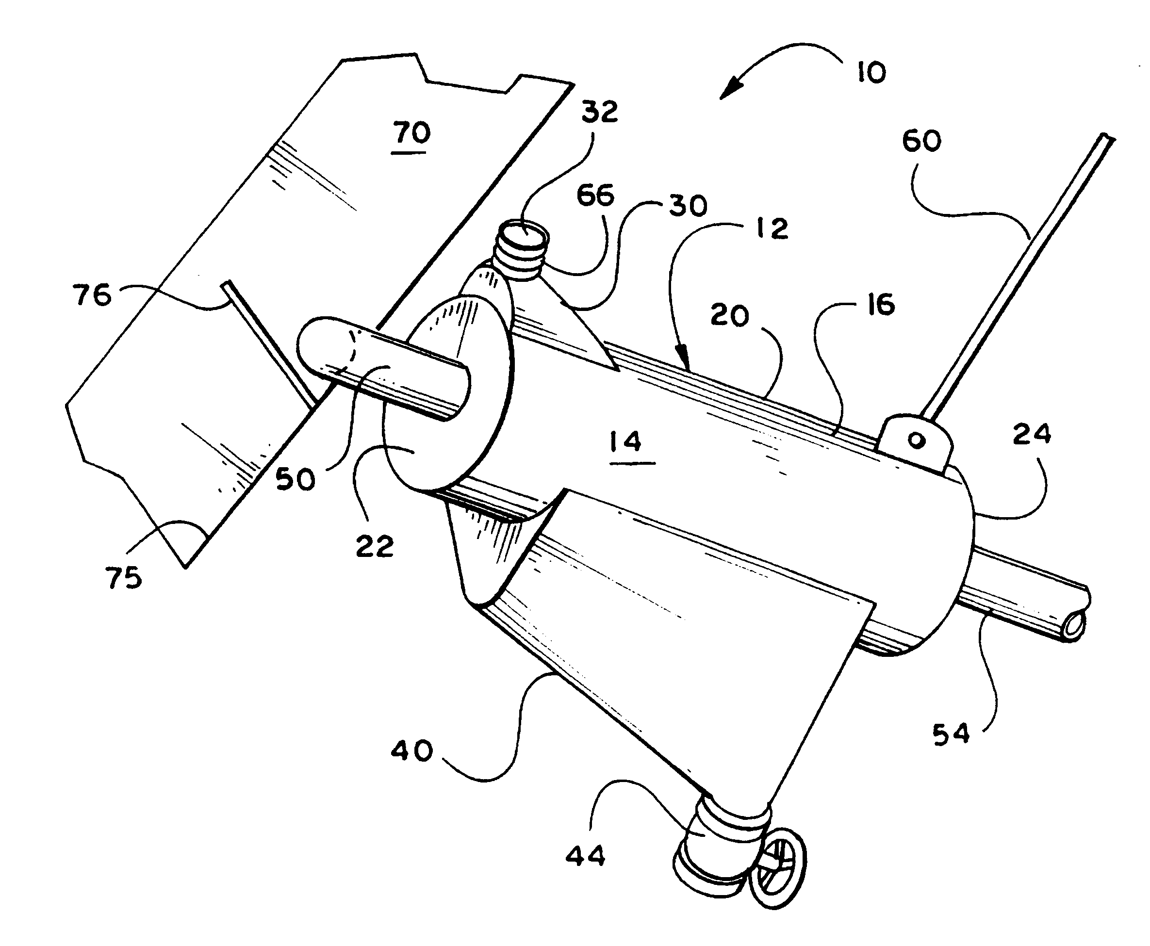
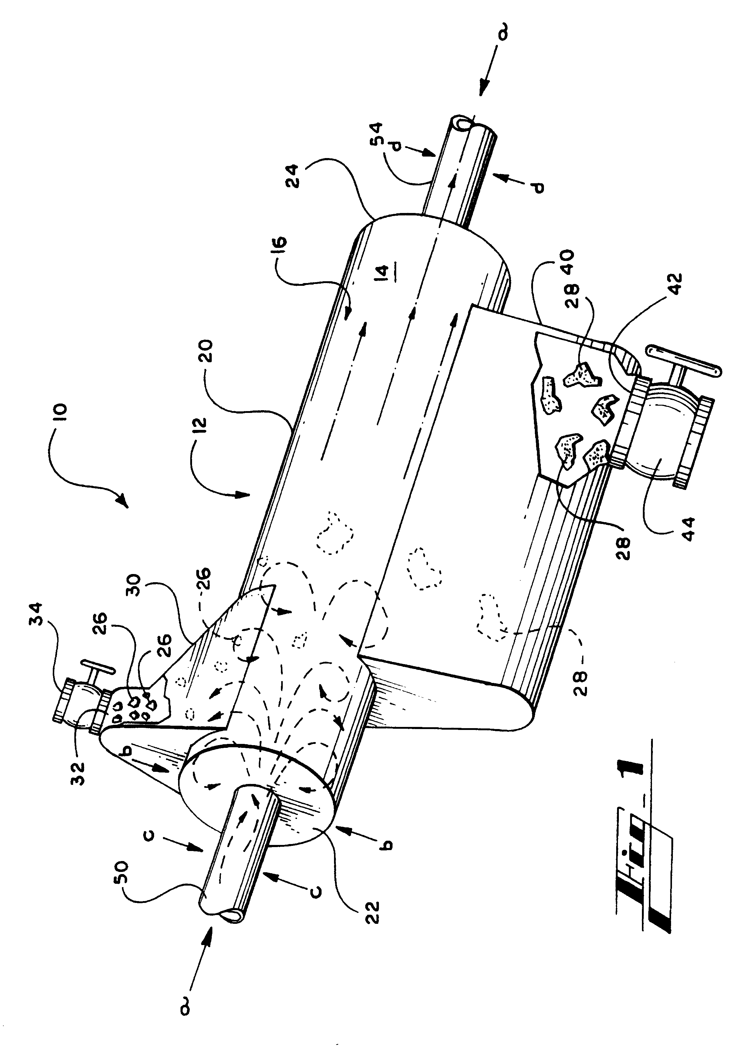
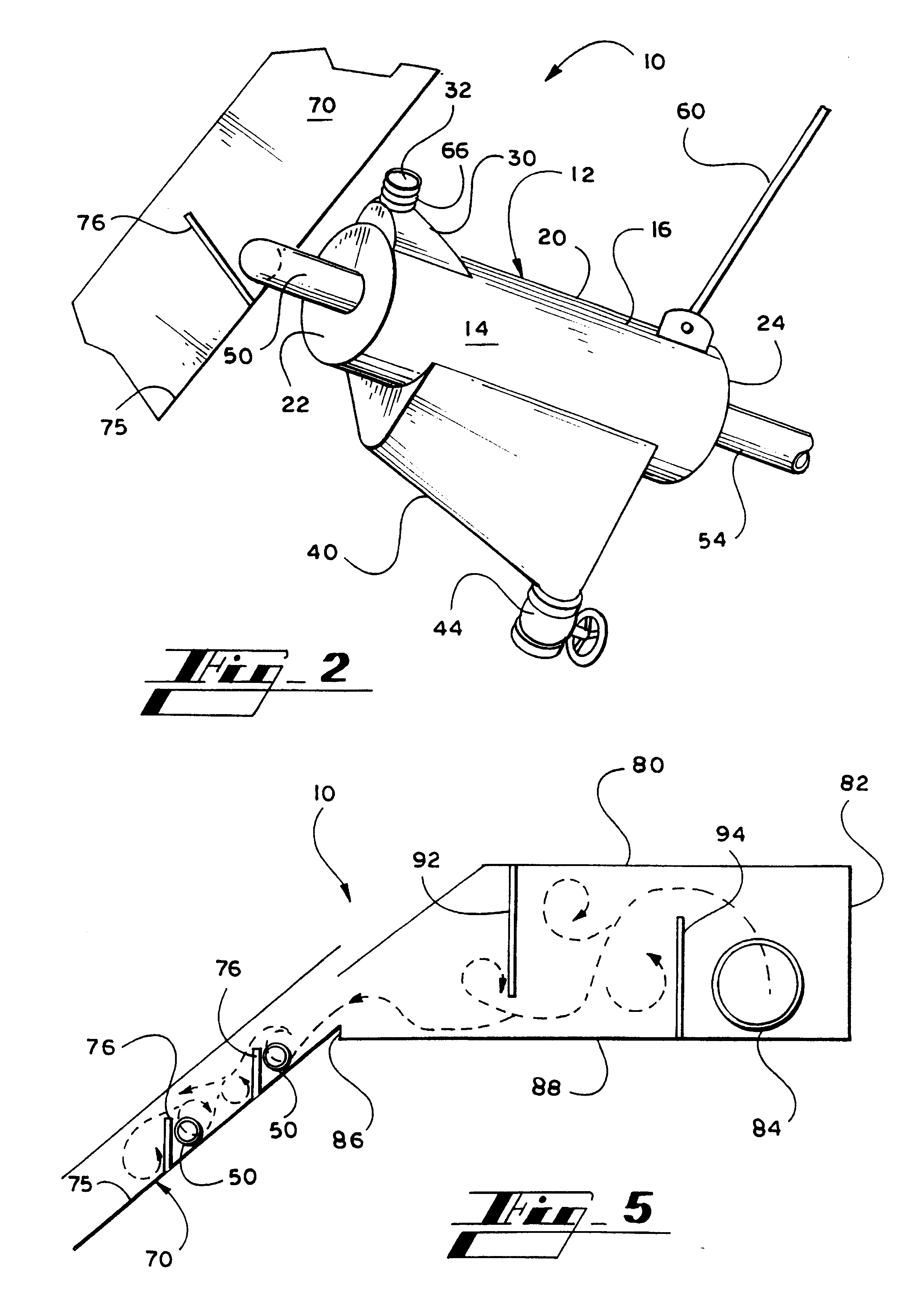
An apparatus for decontaminating aqueous paper pulp is constructed as an elongated, cylindrical cell about 16 inches in length. The cell has an exterior surface and an interior surface defining a pulp decontaminating chamber about 4 inches in diameter. The apparatus also provides an enclosed light contaminate collection hood on the upper exterior surface of the decontaminating cell, which is in fluid communication with the pulp chamber. The hood has an upper port about 1 / 2 inch in diameter for continuously purging light contaminates therethrough.

The cell also has a heavy contaminate collection trough on the lower exterior surface. The collection trough is in fluid communication with the pulp chamber, and has a lower port and a valve for selectively purging heavy contaminates therethrough about 1 inch in diameter.

Pulp is provided to the decontaminating chamber under head from an inlet tube at the upstream pulp receiving end and permitted to flow downstream through the chamber under g...


PUM

PropertyMeasurementUnit
Flow rateaaaaaaaaaa
Lengthaaaaaaaaaa
Ratioaaaaaaaaaa

Abstract

The present invention provides an apparatus for decontaminating aqueous paper pulp, the apparatus comprising a decontaminating cell (12). The decontaminating cell (12) has an upper light contaminate collection hood (30) and / or a lower heavy contaminate collection trough (40). Paper pulp is provided to the cell (12) under a pulp head sufficient to purge the contaminates therefrom.

Description

This invention relates in general to the manufacture of paper products from aqueous paper pulp.In the art of paper manufacturing, decontamination of the paper pulp is of primary importance to achieve a consistent paper product. In particular, recycling waste paper requires extensive cleansing of the aqueous paper pulp to remove extraneous contaminates. Waste paper materials present a challenge to provide an economically feasible means of recycling which yields an acceptable paper product.Contaminates may be grouped into one of three classes. First, elongated flexible materials, such as pieces cord, fabrics and wire can be removed from the pulp relatively efficiently by a ragger, well-known in the art. A ragger is generally a rope trailing in the pulper vat upon which elongated material becomes entwined. Second, heavy materials, such as rocks and metal pieces, are typically removed with increased effort by screen filters or traps. Finally, light weight contaminates, such as plastics,...

Claims


Application Information

Patent Timeline
IPC IPC(8): B03B5/62B03B5/28B03B5/60B03B5/00B03B5/40D21B1/00D21B1/32D21C5/02D21D5/00B01D21/28B03B11/00
CPCB03B5/28B03B5/40B03B5/60B03B5/62D21B1/32D21C5/02D21D5/00Y02W30/64
Inventor LAWSON, J. ALAN
Owner SEP TECH
Why Eureka
Try Eureka