
Process for producing single wall nanotubes using unsupported metal catalysts

Inactive Publication Date: 2001-04-24
HYPERION CATALYSIS INT
View PDF8 Cites 318 Cited by
  • Summary
  • Abstract
  • Description
  • Claims
  • Application Information

AI Technical Summary

Benefits of technology

The invention may in some embodiments employ an aerosol technique in which aerosols of metal containing catalysts are introduced into the reaction mixture. An advantage of an aerosol method for producing SWNT is that it will be possible to produce catalyst particl

Problems solved by technology

Tibbetts reports that these stages are "overlapping", and is unable to grow filaments free of pyrolytically deposited carbon.
First, initiation of fiber growth occurs only after slow carbonization of the steel tube (typically about ten hours), leading to a low overall rate of fiber production.
Second, the reaction tube is consumed in the fiber forming process, making commercial scale-up difficult and expensive.
These techniques are inherently disadvantageous.
Specifically, solid carbon vaporization via electric arc or laser apparatus is costly and difficult to operate on the commercial or industrial scale.
However, supported metal catalysts are inherently disadvantageous, as the support is necessarily incorporated into the single-walled carbon nanotube formed therefrom.
Single-walled nanotubes contaminated with the support material are obviously less desirable compared to single-walled nanotubes not having such contamination.

Method used


Image

  • Process for producing single wall nanotubes using unsupported metal catalysts
  • Process for producing single wall nanotubes using unsupported metal catalysts
  • Process for producing single wall nanotubes using unsupported metal catalysts

Examples


examples 5 and 6

show many areas of SWNT along with MWNT and other carbon structures. Mo particles ranged from <1-10 nm. In Example 4, mainly MWNT were formed along with other structures of carbon. Mo particles ranged from .about.1-50 nm. Presumably, the particles generated in Examples 5 and 6 were the right size to promote SWNT growth over the other forms possible. In Example 4, particle sizes favored growth of MWNT and other forms.

example 1

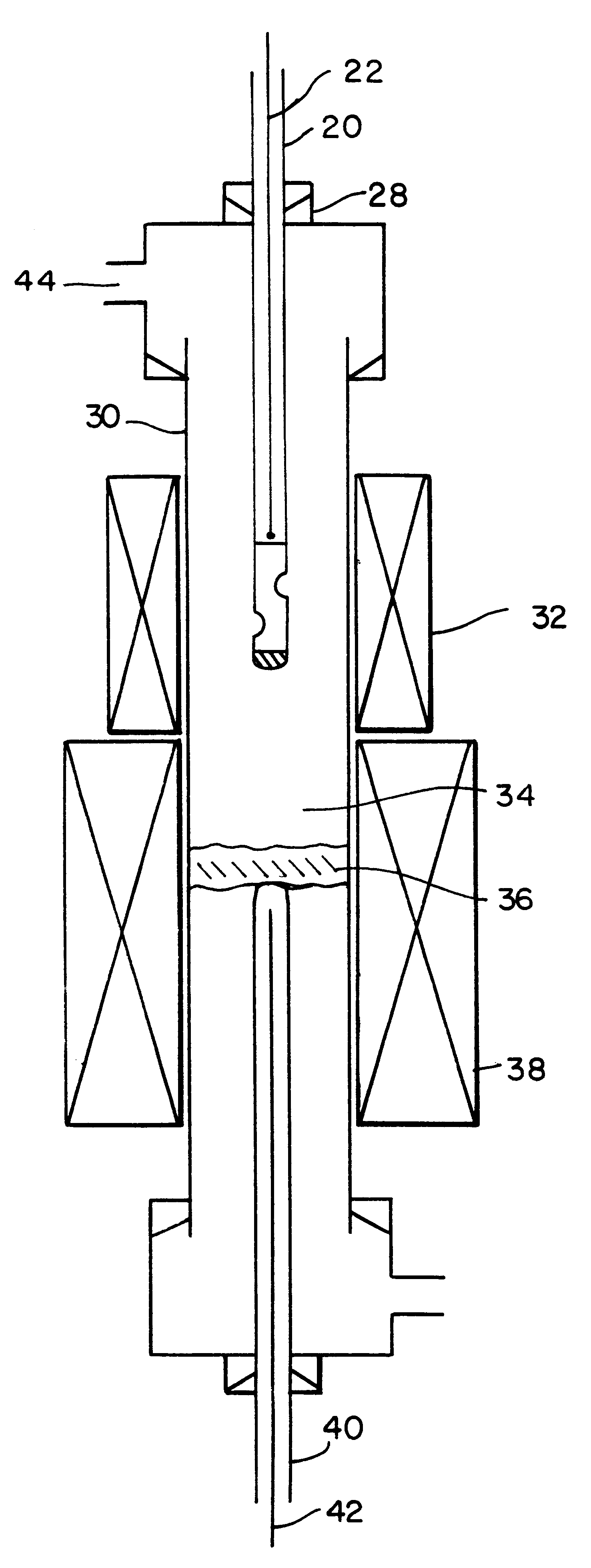
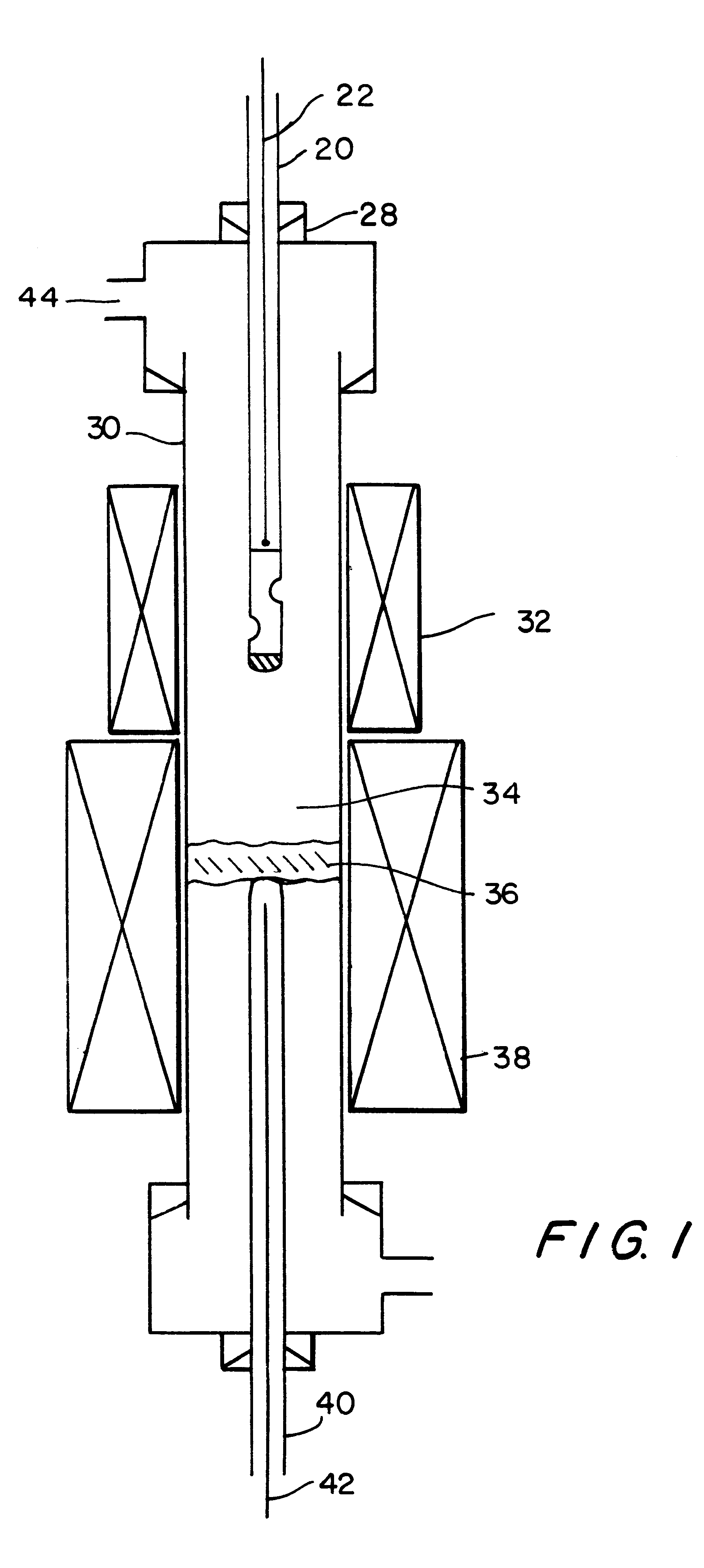
In a direct injection process, the catalyst compartment was loaded with .about.40 mg Molybdenum hexacarbonyl [Mo(CO).sub.6 ] which has been ground to .about.-100 mesh. The reactor was heated to 900.degree. C. under an argon flow. Argon was then replaced with CO at atmospheric pressure at a flow of .about.0.8 SLM and the catalyst was injected.

The flow of Co was continued for 30 min. at 900.degree. C., after which it was replaced by argon, and the reactor furnace turned off. After cooling to ambient temperature, the entire contents of the reactor including the quartz wool plug which had been tared prior to the run, was emptied into a tared plastic bag. The quartz wool plug was blackened, but the yield of carbon growth (wgt C / wgt catalyst) was <1.

A specimen for Transmission Electron Microscopy (TEM) was prepared by shaking the quartz wool plug in ethanol in a glass vial and ultrasounding the ethanol for .about.2 min. This procedure dispersed the black particles from the quartz wool. A ...

example 2

The procedure of Ex. 1 was used to produce a mixture of Mo particles and carbon structures including both MWNT and SWNT. Catalyst charge [Mo(CO).sub.6 ] was .about.8 mg. SWNT yield was <50% of all nanotubes produced.


PUM


Abstract

A process for producing hollow, single-walled carbon nanotubes by catalytic decomposition of one or more gaseous carbon compounds by first forming a gas phase mixture carbon feed stock gas comprising one or more gaseous carbon compounds, each having one to six carbon atoms and only H, O, N, S or Cl as hetero atoms, optionally admixed with hydrogen, and a gas phase metal containing compound which is unstable under reaction conditions for said decomposition, and which forms a metal containing catalyst which acts as a decomposition catalyst under reaction conditions; and then conducting said decomposition reaction under decomposition reaction conditions, thereby producing said nanotubes.

Description

1. Field of the InventionThis invention relates to a method for producing single wall carbon nanotubes, also known as linear fullerenes, employing unsupported metal containing catalysts, for decomposition of a C.sub.1 to C.sub.6 carbon feedstock such as carbon monoxide.2. Description of the Related ArtMulti-walled Carbon NanotubesMulti-walled carbon nanotubes, or fibrils, are well-known. Typically, carbon fibrils have a core region comprising a series of graphitic layers of carbon.Since the 1970's, carbon nanotubes and fibrils have been identified as materials of interest for a variety of applications. Submicron graphitic fibrils belong to a class of materials sometimes called vapor grown carbon fibers. Carbon fibrils are vermicular carbon deposits having diameters less than approximately 1.0.mu.. They exist in a variety of forms and have been prepared through the catalytic decomposition of various carbon-containing gases at metal surfaces. Such vermicular carbon deposits have been ...

Claims


Application Information

Patent Timeline
IPC IPC(8): C01B31/00C01B31/02D01F9/127D01F9/12B01J3/04B01J19/12B01J19/26
CPCB01J3/04B01J3/042B01J19/121B01J19/26B82Y30/00B82Y40/00C01B31/0233D01F9/127D01F9/1278B01J2219/0875C01B2202/02Y10S977/742Y10S977/896Y10S977/75Y10S977/843Y10S977/842C01B32/162
Inventor MOY, DAVIDCHISHTI, ASIF
Owner HYPERION CATALYSIS INT
Learn More