High-resolution large-field-of-view three-dimensional hologram display system and method thereof

Inactive Publication Date: 2001-02-27
NASA
View PDF22 Cites 130 Cited by
  • Summary
  • Abstract
  • Description
  • Claims
  • Application Information

AI Technical Summary

Benefits of technology

A key application of this 3-D display technology in support of Battlespace Visualization, is its potential to accurately portray threat envelopes from enemy radars or other observing systems. Presently, radar threat and line-of-sight models identify areas that are illuminated or shadowed by terrain, but only for the 2-D case (i.e. height of the observer and potential target is fixed). A 3-D rendition will more fully portray the real impact of terrain shadowing upon multiple search fans, thereby revealing potential areas of undetected movement. For friendly forces, the 3-D display will provide a comprehensive collection management and asset management tool that assures complete, or the most effective coverage, in regions of moderate or high relief. This invention is implemented by the use of a pure form of silica Aerogel as the display medium for 3-D holograms. This innovative display technique may lead to a number of new military and commercial applications.
Monolithic Aerogel is produced by a batch process and is limited in size by current process equipment and practices. With existing processing equipment, a 10 cm.sup.3 cube has been produced. With proper equipment and process development, larger monoliths will be possible. The backscattering efficiency of the Aerogel should be as high as possible to enhance the angular visibility of the 3-D hologram displayed in an Aerogel matrix.

Problems solved by technology

However, the lack of an ideal display medium and apparatus has been the primary limiting factor for obtaining a practical system.
However, the fact that viewer has to wear polarizing goggles, with a narrow field of view, severely limits its visualization applications.
The volume of this displayed image is limited due to the need of spinning a large screen at a high speed.
Thus, vertical movement on the part of the viewer will not provide a new perspective.
Monolithic Aerogel is produced by a batch process and is limited in size by current process equipment and practices.
While computer generation of 3-D images has been demonstrated, overcoming the matrix problem has been elusive until now.

Method used


Image

  • High-resolution large-field-of-view three-dimensional hologram display system and method thereof
  • High-resolution large-field-of-view three-dimensional hologram display system and method thereof
  • High-resolution large-field-of-view three-dimensional hologram display system and method thereof

Examples


Embodiment Construction

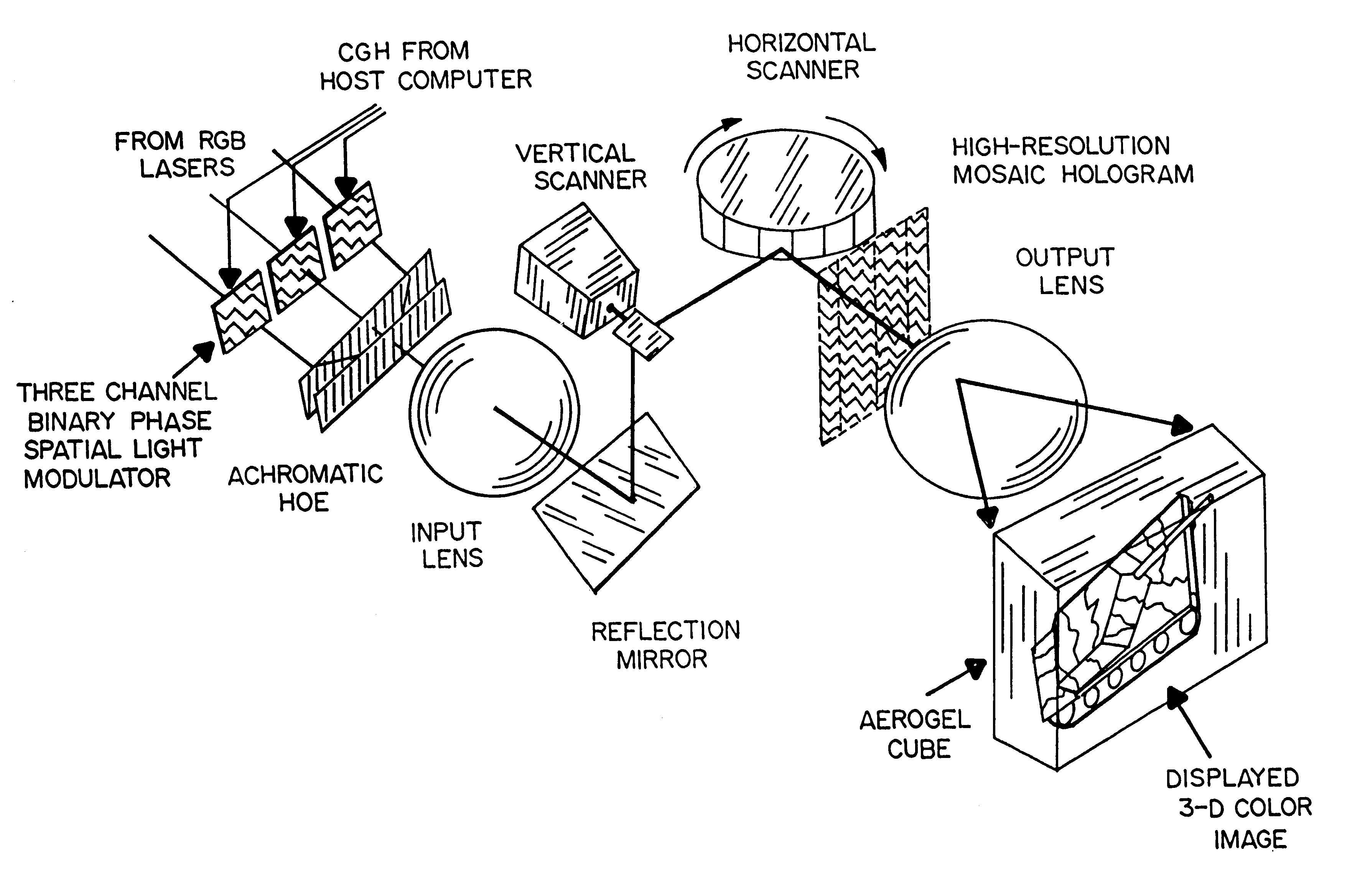
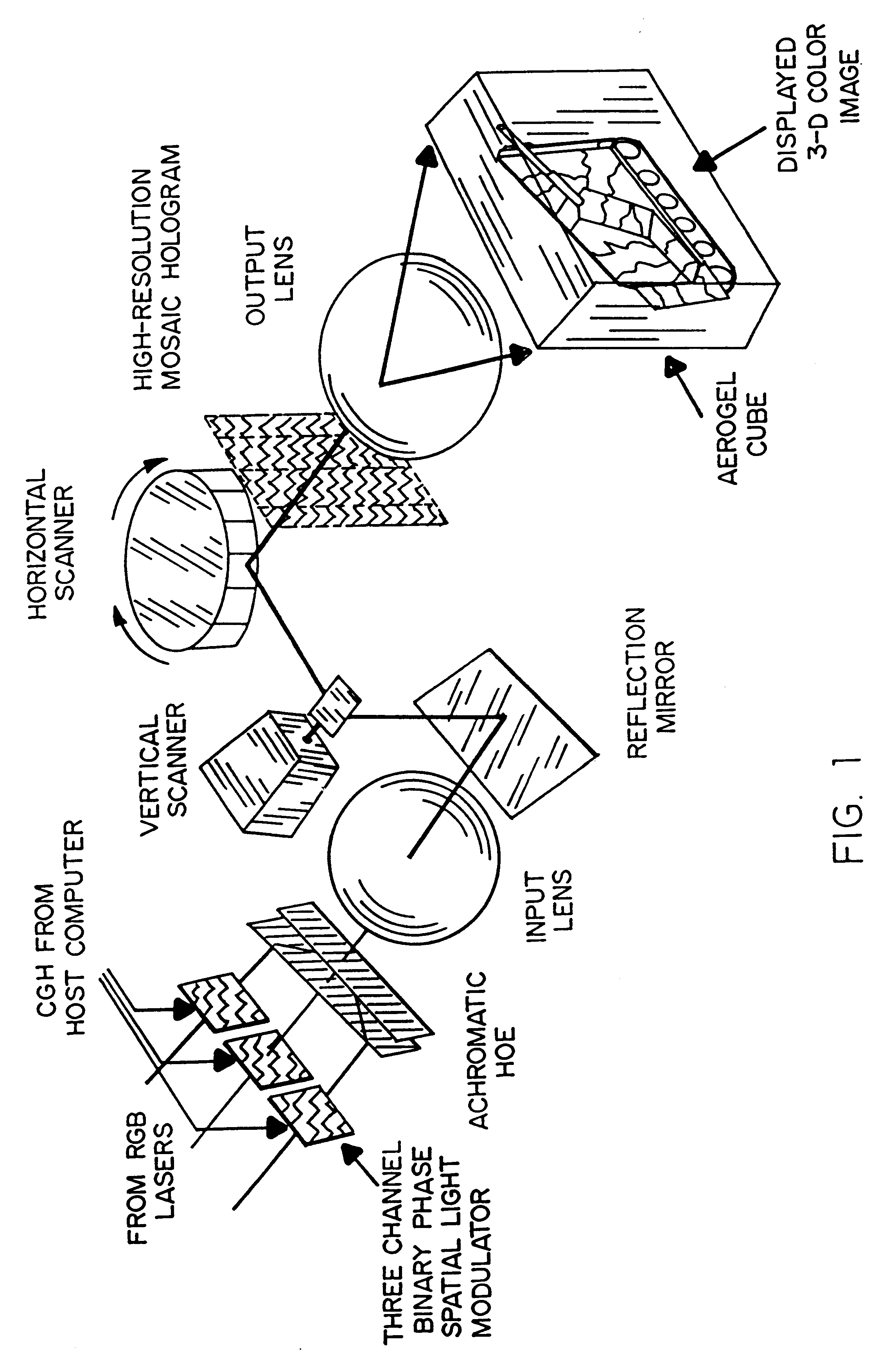
Referring to FIG. 1, it will be seen that a display system in accordance with the present invention comprises a three-channel binary phase, spatial light modulator, an achromatic HOE, an input lens, a mirror, a vertical scanner, a horizontal scanner, an output lens and an Aerogel display medium. The holographic source shown in FIG. 1 comprises a computer generated hologram (CGH) from a host computer. The CGH is used as a modulation signal to a set of spatial light modulators through which respective red, green and blue reference laser light is transmitted. The spatial light modulators are liquid crystal devices having a two-dimensional array of individually modulated pixels, each capable of numerous discrete levels of transmissivity depending upon the modulation level.

The output of the three channel spatial light modulator is applied to an achromatic hologram optical element (HOE) which is, in effect, an optical combiner providing a unitary colored holographic optical signal with a ...


PUM


Abstract

A real-time, dynamic, free space-virtual reality, 3-D image display system which is enabled by using a unique form of Aerogel as the primary display media. A preferred embodiment of this system comprises a 3-D mosaic topographic map which is displayed by fusing four projected hologram images. In this embodiment, 4 holographic images are projected from 4 separate holograms. Each holographic image subtends a quadrant of the 4pi solid angle. By fusing these four holographic images, a static 3-D image such as a featured terrain map would be visible for 360 degrees in the horizontal plane and 180 degrees in the vertical plane. An input, either acquired by 3-D image sensor or generated by computer animation, is first converted into a 2-D computer generated hologram (CGH). This CGH is then downloaded into large liquid crystal (LC) panel. A laser projector illuminates the CGH-filled LC panel and generates and displays a real 3-D image in the Aerogel matrix.

Description

The present invention relates generally to three-dimensional (3-D), hologrammetric display of objects (photographed or reconstituted by computer graphics) in a display matrix such that a dynamic scene can be viewed from any angle in the x, y or z axes. The invention relates more specifically to the display of 3-D map products for strategic or tactical planning to enhance the ability of commanders and their support staff to understand and exchange command and control information; particularly with respect to Battlefield Visualization.Prior to the present invention, viewers of (so called) three-dimensional (3-D) holograms were required to view the reflected image(s) within the line-of-sight range of a holographic projection plate. If the viewer's eyes were moved out of the narrow range of the reflected images, the image would "disappear". In essence, the viewer's eyes were the "display medium" for the hologrammetric images.Real time, 3-D image display has been the focus of many develo...

Claims


Application Information

Patent Timeline
IPC IPC(8): G03H1/08G03H1/00G03H1/24
CPCG03H1/08G03H1/2294G03H1/24G03H2001/2213G03H2001/2263G03H2001/2292G03H2001/306G03H2222/18G03H1/2249G03H2210/30
Inventor CHAO, TIEN-HSINMINTZ, FREDERICK W.TSOU, PETERBRYANT, NEVIN A.
Owner NASA
Why Eureka
Try Eureka