Eureka AIR delivers breakthrough ideas for toughest innovation challenges, trusted by R&D personnel around the world.

Light bulb shaped lamp

Active Publication Date: 2012-06-28
SATCO PRODS
View PDF13 Cites 74 Cited by
  • Summary
  • Abstract
  • Description
  • Claims
  • Application Information

AI Technical Summary

Benefits of technology

[0005]The incandescent light bulb with the filament that can be seen through the globe is mainly used for decoration. Luminance that allows directly viewing the filament and high luminous flux that would brighten up an area around the light bulb are required for the incandescent light bulb. Accordingly, when replacing the incandescent light bulb with LED light bulb, luminance and luminous flux equivalent to those of the incandescent light bulb are required for the LED light bulb. Higher efficiency and longer lifetime than those of the incandescent light bulb are required for the LED light bulb as well.
[0011]With this configuration, it is possible to simplify the component structure.
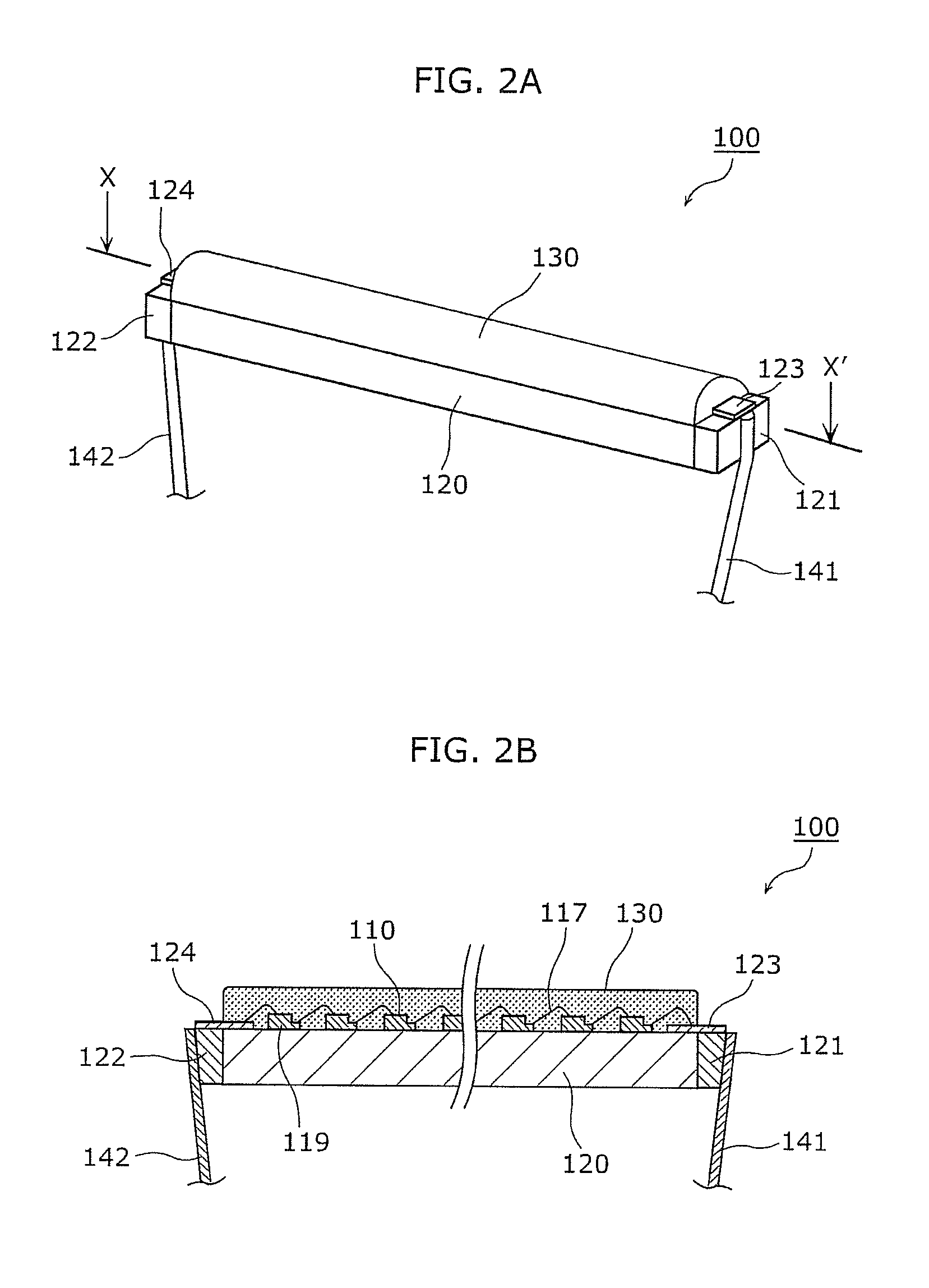
[0014]With this configuration, it is possible to protect the light-emitting device with the sealing material. Furthermore, by covering the light-emitting device with the translucent material, twinkling light is emitted when the electric bulb shaped lamp is turned on.
[0035]The present invention can reproduce the simulated light-emission state of the filament in a conventional incandescent light bulb emitting light. Furthermore, in the present invention, it is not necessary to use optical fibers. Thus, no coupling loss described above occurs, implementing an LED light bulb with high efficiency and high luminous flux.

Problems solved by technology

Meanwhile, some manufacturers stop manufacturing incandescent light bulbs using filaments (filament coils).

Method used


Image

  • Light bulb shaped lamp
  • Light bulb shaped lamp
  • Light bulb shaped lamp

Examples


embodiment 1

[0055]First, the light bulb shaped lamp according to the embodiment 1 of the present invention shall be described. The light bulb shaped lamp according to the embodiment 1 of the present invention is a light bulb shaped lamp in which LED is used as the light source, and is the LED light bulb replacing conventional light bulb shaped lamp such as incandescent light bulbs and light bulb shaped fluorescent lamps.

Overall Configuration of LED Light Bulb

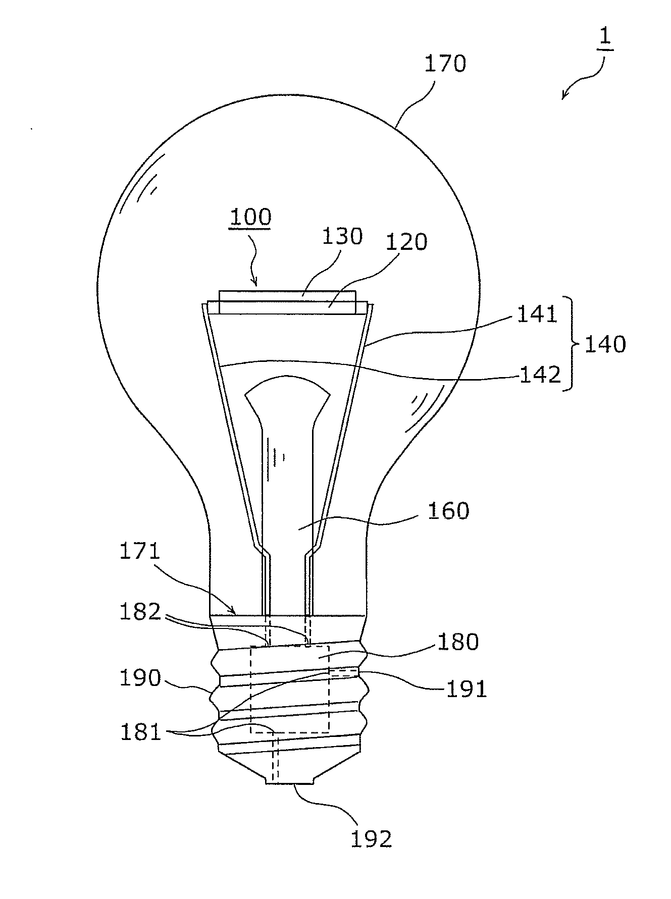
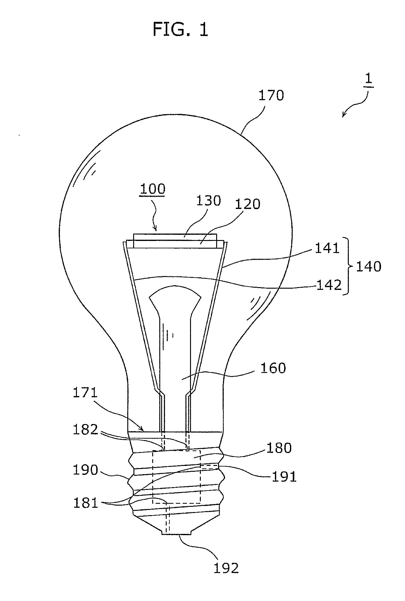
[0056]The overall configuration of the LED light bulb according to the embodiment 1 of the present invention shall be described with reference to FIG. 1. FIG. 1 is a top view of the LED light bulb according to the embodiment 1 of the present invention.

[0057]As illustrated in FIG. 1, the LED light bulb 1 according to the embodiment 1 of the present invention uses LED chips which are semiconductor light-emitting devices as the light source. The LED light bulb 1 includes a filament part 100 composed of the LED chips and other parts, two power...

embodiment 2

[0106]Next, an LED light bulb 2 according to the embodiment 2 of the present invention shall be described with reference to FIGS. 7 to 9. FIG. 7 is a front view of the LED light bulb according to the embodiment 2 of the present invention.

[0107]As illustrated in FIG. 7, the LED light bulb 2 according to the embodiment 2 of the present invention is different form the LED light bulb 1 according to the embodiment 1 in that a spherical (Type G) globe 370 is used, that the LED chips 310 are mounted on both surfaces of the base board 320, and that the two rows of LED chips (series connected group) that were connected in series are inversely connected in parallel.

[0108]FIG. 8A is a top view of the filament part 300 in the embodiment 2. The filament part 300 is formed as follows: a plurality of LED chips 310 are arranged in a zigzag line and mounted on translucent base board 320; the sealing material 330 including the wavelength conversion material is applied in zigzag shape along the LED ch...


PUM


Abstract

A light bulb shaped lamp according to the present invention includes a translucent base board, an LED chip mounted on the base board, a base for receiving power from outside, at least two power-supply leads for supplying power to the LED chip, and a globe partially attached to the base for housing the base board, the LED chip, and the power-supply leads. Each of the two power-supply leads extends from a side of the base toward inside of the globe and connected to the base board, and the LED chip is provided between a portion at which one of the two power-supply leads and the base board are connected and a portion at which the other of the two power-supply leads and the base board are connected.

Description

TECHNICAL FIELD [0001]The present invention relates to LED light bulbs including light-emitting devices, and particularly relates to a light bulb shaped LED lamp having a light-emitting diode (LED).BACKGROUND ART [0002]Compared to conventional illumination light source, semiconductor light emitting devices such as LEDs are small, have high efficiency and long lifetime as a light source. Recent market needs for saving energy and resource boosts the demand for light bulb shaped lamps using LEDs (hereafter simply referred to as “LED light bulb”) and lighting apparatuses including the LED light bulbs. Meanwhile, some manufacturers stop manufacturing incandescent light bulbs using filaments (filament coils).[0003]For example, the patent literature 1 discloses a conventional LED light bulb reproducing the shape of conventional filament in an incandescent light bulb. In the LED light bulb disclosed in the patent literature 1, an optical fiber resembling the shape of a filament is housed ...

Claims


Application Information

Patent Timeline
IPC IPC(8): F21V9/16
CPCF21K9/135F21V3/00F21Y2101/02F21Y2103/003F21Y2105/001H01L33/48H01L2224/45144H01L2224/49107H01L2224/73265H01L2924/00F21Y2105/10F21K9/64F21Y2103/10F21Y2115/10H01L2924/00011H01L2224/4903H01L2924/19107F21K9/232F21V3/08F21V9/32H01L2924/00014H01L2224/45147H01L2924/01033F21V29/70F21K9/238F21K9/235F21K9/237F21V3/02F21V9/08F21V19/005F21V23/002F21V31/005F21K9/66H01L25/0753H01L33/32H01L33/502H01L33/507H01L33/52H01L33/62H01L33/505H01L33/54H01L33/647
Inventor TAKEUCHI, NOBUYOSHIMATSUDA, TSUGIHIRONAGAI, HIDEOMIKI, MASAHIROKURIMOTO, YOSHITAKA
Owner SATCO PRODS
Why Eureka
Eureka Blog
Learn More