
Glass induction melting furnace using a cold crucible

a glass induction melting furnace and cold crucible technology, applied in the field of embolism, can solve the problems of complex furnace type, refractory pollution, and crucible type not being compatible with all melting baths

Inactive Publication Date: 2001-02-06
COMMISSARIAT A LENERGIE ATOMIQUE ET AUX ENERGIES ALTERNATIVES
View PDF11 Cites 29 Cited by
  • Summary
  • Abstract
  • Description
  • Claims
  • Application Information

AI Technical Summary

Benefits of technology

The average diameter of the induction coil is approximately half the diameter of an induction coil that would conventionally be wound around the crucible, which significantly reduces its inductance and therefore its excitation voltage. The components supplying the excitation voltage can therefore be less expensive for a given crucible diameter, or existing components may be used to make a crucible with a larger diameter.
Moving the periphery of the induction coil away from the crucible side walls means that a thick layer of solidified glass can be obtained on these side walls which reduces heat losses between the melting bath and the cooled crucible. This type of thermal insulation cannot be obtained for metals, which are good thermal conductors both in the liquid state and in the solid state.
According to one embodiment of this invention, the furnace comprises a metal base and lid which, together with the crucible to which they are connected, form a Faraday cage protecting the external environment from the radiation produced by the induction coil.

Problems solved by technology

The most widely used and the simplest crucibles are made of refractory material, but this type of crucible is not compatible with all melting baths.
Some materials are corrosive to refractory materials when they melt whereas others, and particularly glass, may be polluted by the refractory materials.
However, this lower induction coil only forms a makeup heating element.
The induction coil is designed to determine the pour temperature, this pour taking place in the middle of the induction coil, but it is not used and it is not designed to melt the entire quantity of metal contained in the crucible.
This type of furnace is complicated to make, particularly if it is to be made with cold walls.
This type of thermal insulation cannot be obtained for metals, which are good thermal conductors both in the liquid state and in the solid state.
For metals, the performances of this type of furnace are not very good compared with what can be obtained in conventional furnaces.

Method used


Image

  • Glass induction melting furnace using a cold crucible
  • Glass induction melting furnace using a cold crucible
  • Glass induction melting furnace using a cold crucible

Examples


Embodiment Construction

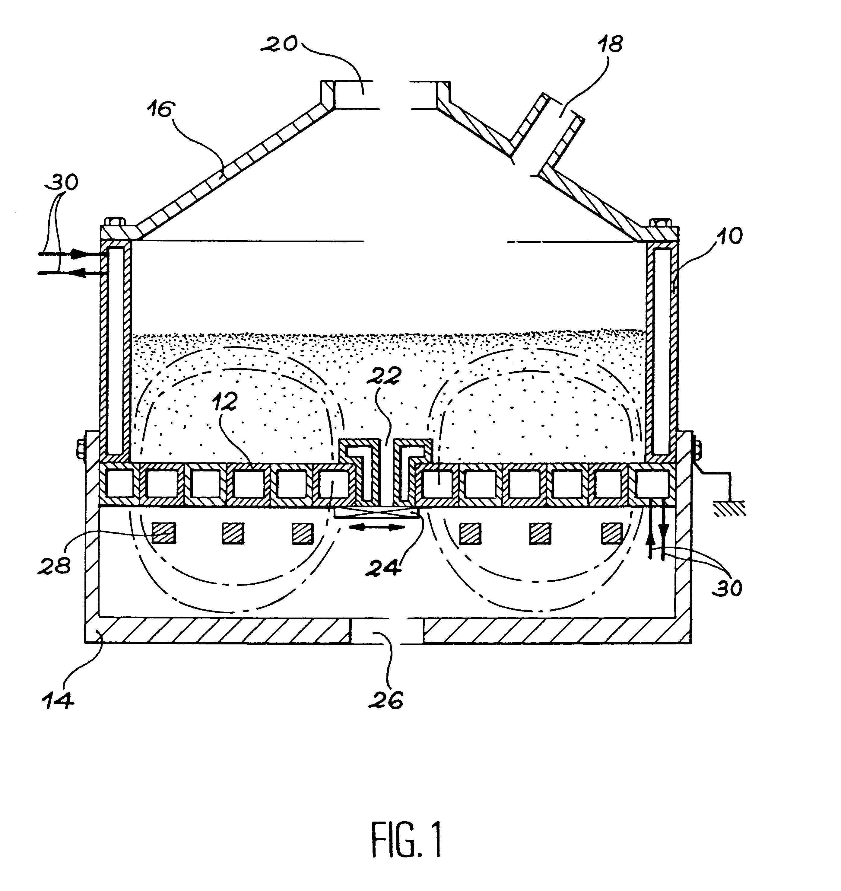
FIG. 1 shows an embodiment of a glass melting furnace according to the invention, and comprises a cooled crucible composed of a vertical ring segment 10 with a double metal wall placed on a horizontal bottom 12 transparent to the electromagnetic field. For example, this assembly may he placed on a bowl shaped base 14. It may be covered by a lid 16 that includes several access orifices, namely a material inlet orifice 18 and a combustion gas exhaust flue 20. For example, the bottom 12 may include a central outlet orifice 22 closed off by a withdrawable door 24. The base 14 then includes a corresponding outlet orifice 26.

The only induction heating element 28 is placed immediately under the bottom 12, inside tank 14. In this embodiment, this heating element is an induction coil with one or several turns.

The vertical ring segment 10 and the bottom 12 are each designed to enable circulation of cooling liquid which is shown by ducts 30 shown diagrammatically. The ring segment comprises co...


PUM

PropertyMeasurementUnit
Thicknessaaaaaaaaaa

Abstract

A melting furnace for insulating materials is provided with a cooled crucible (10) having continuous metal side malls, a partitioned and cooled bottom (12) and at least one induction coil (28) placed under the bottom which serves as the sole heating means. The depth of the melting bath contained in the crucible and the excitation frequency of the induction coil are selected so that the depth and half of the inside radius of the crucible are less than the skin thickness of the bath.

Description

This invention relates to melting of insulating materials such as glass, by direct induction in a cold crucible.PRIOR ART AND PROBLEMS CAUSEDAny materials may be made by melting in crucibles heated with induction. The most widely used and the simplest crucibles are made of refractory material, but this type of crucible is not compatible with all melting baths. Some materials are corrosive to refractory materials when they melt whereas others, and particularly glass, may be polluted by the refractory materials.These materials then have to be prepared in special crucibles called "cold" crucibles which have non-polluting walls. A cold crucible is composed of metal sectors cooled by water circulation in which the material to be prepared is heated by a peripheral induction coil. Separating the crucible into sectors, or partitioning, limits temperature rises due to induction in the crucible wall, and enables direct induction heating of the material contained in the furnace.The induction c...

Claims


Application Information

Patent Timeline
IPC IPC(8): C03B5/00C03B5/02C03B5/26C03B5/44F27B14/10F27B14/00F27B14/06H05B6/24H05B6/36H05B6/02F27B14/08C03B5/08C03B5/235C03B5/42F27D11/06H05B6/44
CPCC03B5/021C03B5/26C03B5/44F27B14/063F27B14/10H05B6/24H05B6/367C03B2211/70F27B2014/0881H05B6/36
Inventor BOEN, ROGERBONNETIER, ARMANDLADIRAT, CHRISTIAN
Owner COMMISSARIAT A LENERGIE ATOMIQUE ET AUX ENERGIES ALTERNATIVES
Learn More