
Exhaust switch-over valve malfunction detection system of internal combustion engine

a technology of malfunction detection and exhaust switchover valve, which is applied in the direction of service pipe systems, machines/engines, electric control, etc., can solve the problems of valve leakage, malfunction detection accuracy degradation, and inability to achieve exhaust gas purification in this kind of system

Inactive Publication Date: 2001-02-06
HONDA MOTOR CO LTD
View PDF7 Cites 63 Cited by
  • Summary
  • Abstract
  • Description
  • Claims
  • Application Information

AI Technical Summary

Problems solved by technology

However, when the engine is cold started, for example, and the catalyst is not activated, unburned components of the exhaust gas, in particular, unburned HC are relesed immediately into the atmosphere.
No exhaust gas purification can be achieved in this kind of system if the switch-over valve malfunctions, Japanese Laid-Open Patent Application No.
When the result is negative, it is also determined that the valve leaks.
Since, however, the detections are conducted at different times, the engine operation, if it is under steady-state, may be different, in precise speaking, from each other in between these detection times, rendering the malfunction detection accuracy degraded.

Method used


Image

  • Exhaust switch-over valve malfunction detection system of internal combustion engine
  • Exhaust switch-over valve malfunction detection system of internal combustion engine
  • Exhaust switch-over valve malfunction detection system of internal combustion engine

Examples


Embodiment Construction

Embodiments of the invention will now be explained with reference to the drawings.

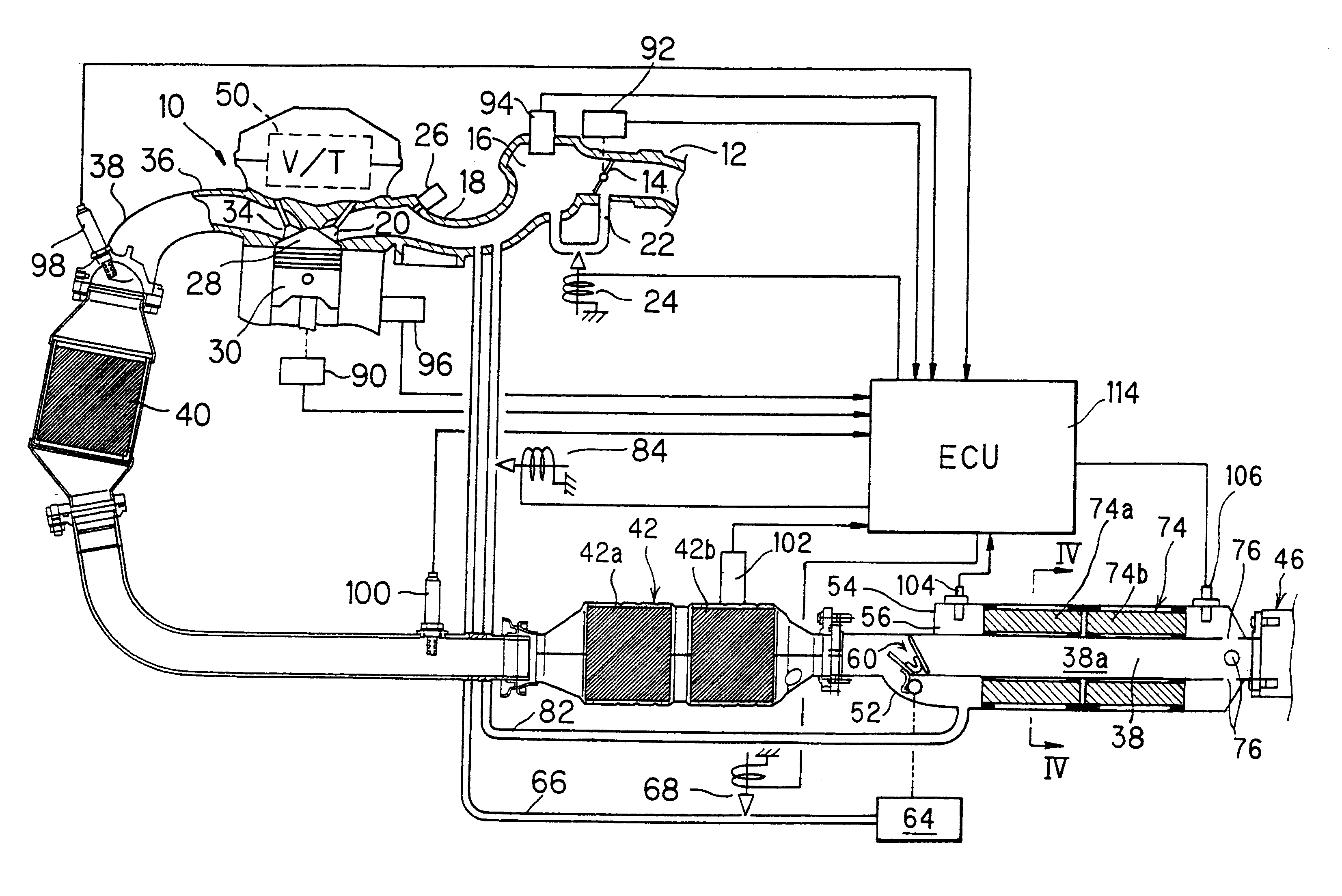
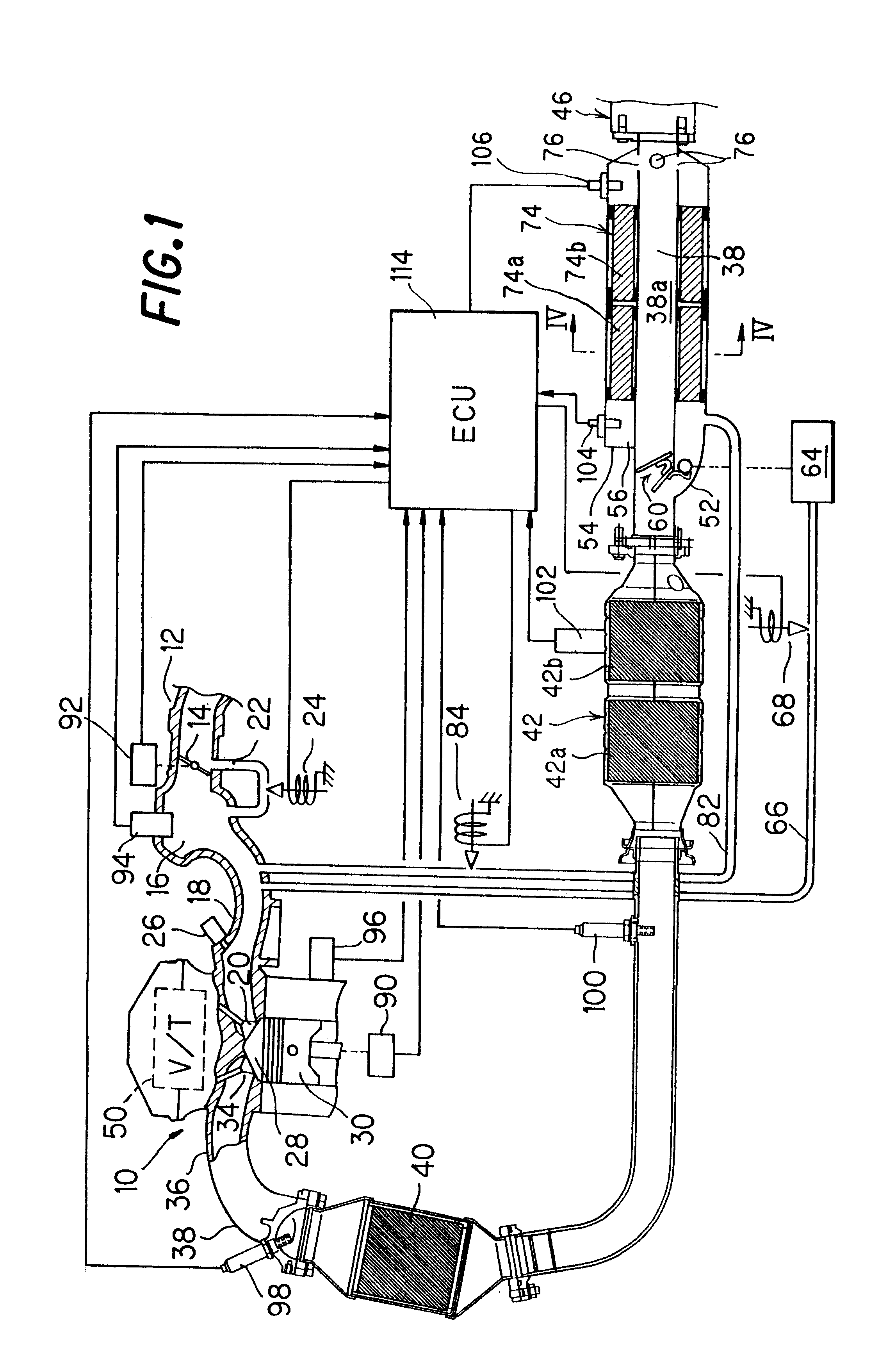
FIG. 1 is a view schematically showing the overall configuration of an exhaust switch-over valve malfunction detection system of an internal combustion engine according to the invention.

Reference numeral 10 in this figure designates an overhead cam (OHC) in-line four-cylinder internal combustion engine. Air drawn into an air intake pipe or passage 12 through an air cleaner (not shown) mounted separately is supplied to the first to fourth cylinders (only one is shown) through a surge tank 16, an intake manifold 18 and two intake valves 20 (only one is shown), while the flow thereof is adjusted by a throttle valve 14. The throttle valve 14 is bypassed by a bypass 22 provided at the air intake pipe 12. A valve (EACV) 24 comprised of an electromagnetic solenoid valve is installed in the bypass 22 for closing the same.

A fuel injector 26 is installed in the vicinity of the intake valves 20 of each cylinder f...


PUM


Abstract

A system for detecting malfunctions of an exhaust switch-over valve of an internal combustion engine, which opens / closes a bypass exhaust gas passage branched from an exhaust pipe of the engine and storing an adsorbent that adsorbs unburned components of the exhaust gas generated by the engine when the engine is started. In the system, the entrance temperature and the exit temperature in the bypass exhaust gas passage are detected and compared with each other in a first detection period when the passage is opened and in a second detection period when the passage is closed. Based on this comparison, it is determined whether the valve malfunctions. Alternatively, the valve malfunction is determined by comparing the valve opening / closing state with an instruction to operate the valve. With this, little time lag exists in the detection, thereby improving malfunction detection accuracy.

Description

1. Field of the InventionThis invention relates to an exhaust switch-over valve malfunction detection system of an internal combustion engine with an exhaust gas purification system that includes an adsorber (stored in a bypass branched from the exhaust pipe that is opened / closed by a swtich-over valve) which adsorbs unburned components such as the hydrocarbon (HC) content of the exhaust gas generated by the engine. This enhances exhaust gas purification, more particularly the invention acts as a system for detecting switch-over valve malfunctions provided at the branching point to selectively open / close the bypass.2. Description of the Related ArtInternal combustion engines are ordinarily provided with a catalyst (a three-way catalytic converter) in the exhaust system which removes HC, NOx and CO components in the exhaust gas generated by the engine. However, when the engine is cold started, for example, and the catalyst is not activated, unburned components of the exhaust gas, in ...

Claims


Application Information

Patent Timeline
Patent Type & Authority Patents(United States)
IPC IPC(8): F01N3/08F01N11/00F01N7/00F01N7/02F02M25/07F02D9/04F01N3/20F01N13/02F02D41/22
CPCF01N3/0814F01N3/0835F01N3/0878F01N3/101F01N11/00F01N11/002F02D41/221F02M25/0718F01N13/0093F01N13/009F01N13/0097F01N2550/06F01N2900/0422Y02T10/40Y02T10/47Y02T10/22F02M26/15Y02T10/12Y10T137/8158
Inventor YAMAZAKI, HIDEHARUYASUI, YUJIHAGA, TAKASHISAITO, KATSUMIIWAKI, YOSHIHISA
Owner HONDA MOTOR CO LTD
Learn More