
Time-Warping of Decoded Audio Signal After Packet Loss

a decoded audio and packet loss technology, applied in the field of timewarping of decoded audio signals after packet loss, can solve the problems of significant degradation of audio quality, and the inability to apply the techniques described in these applications directly to sub-band predictive coders

Active Publication Date: 2008-02-21
AVAGO TECH INT SALES PTE LTD
View PDF48 Cites 41 Cited by
  • Summary
  • Abstract
  • Description
  • Claims
  • Application Information

AI Technical Summary

Benefits of technology

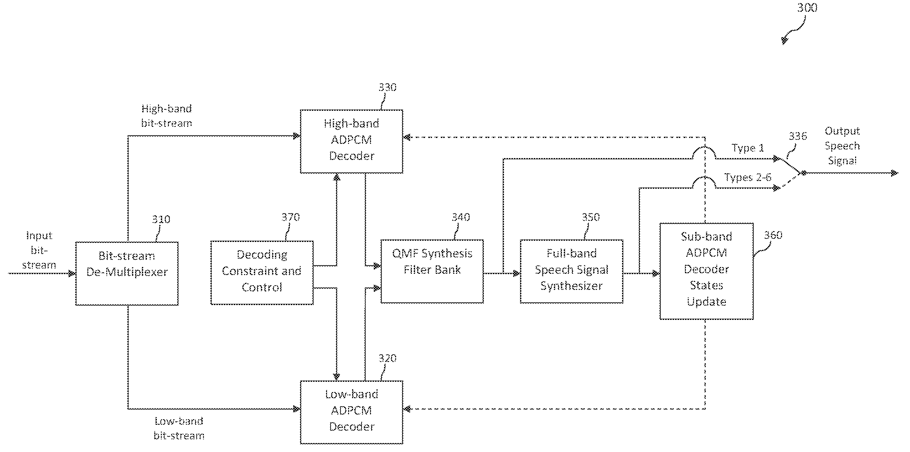
[0007]The present invention is useful for concealing the quality-degrading effects of packet loss in a sub-band predictive coder. It specifically addresses some sub-band-specific architectural issues when applying aud

Problems solved by technology

Sometimes some packets are lost, and sometimes some packets arrive too late to be useful, and therefore are deemed lost.
Such packet loss will cause significant degradation of audio quality unless special techniques are used to conceal the effects of packet loss.
Such PLC methods include the techniques described in U.S. patent application Ser. No. 11 / 234,291 to Chen entitled “Packet Loss Concealment for Block-Independent Speech Codecs” and U.S. patent application Ser. No. 10 / 183,608 to Chen entitled “Method and System for Frame Erasure Concealment for Predictive Speech Coding Based on Extrapolation of Speech Waveform.” However, the techniques described in these applications cannot be directly applied to sub-band predictive coders such as the ITU-T Recommendation G.722 wideband speech coder because there are sub-band-specific structural issues that are not addressed by those techniques.
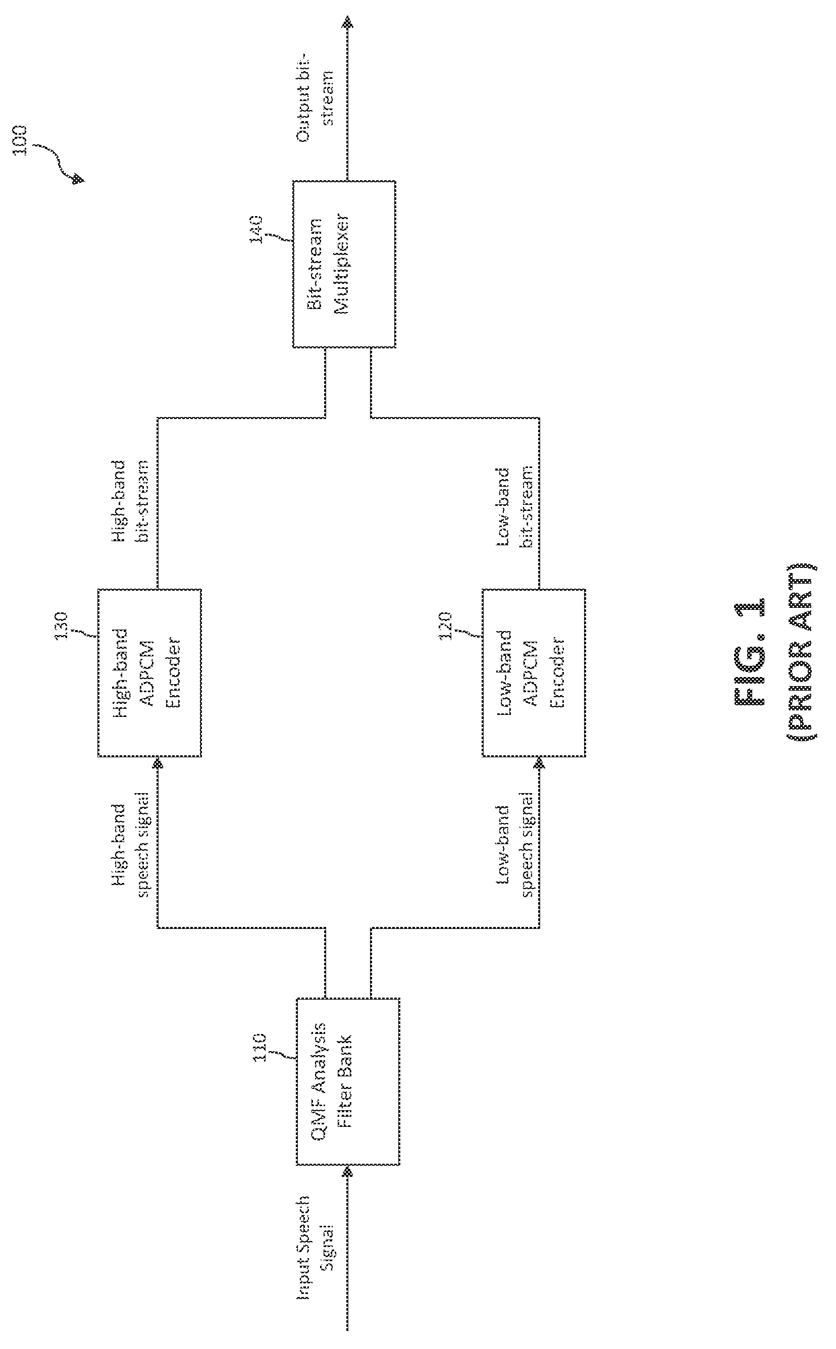
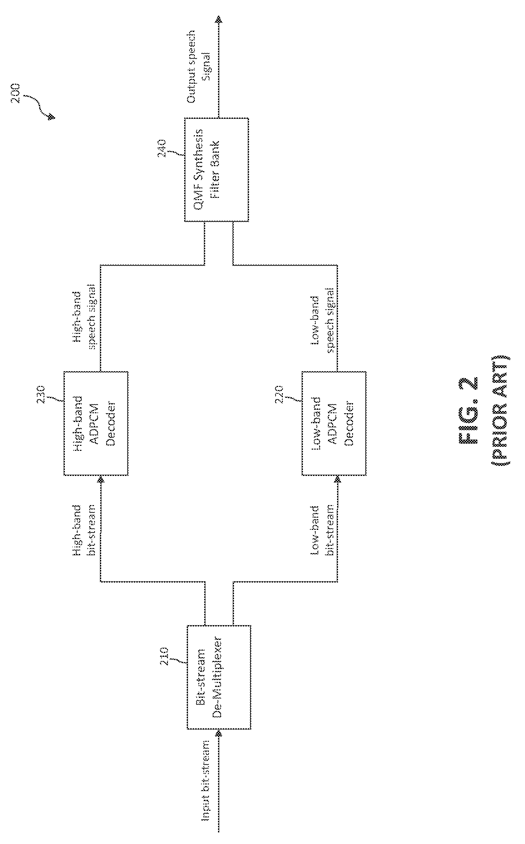
Furthermore, for each sub-band the G.722 coder uses an Adaptive Differential Pulse Code Modulation (ADPCM) predictive coder that uses sample-by-sample backward adaptation of the quantizer step size and predictor coefficients based on a gradient method, and this poses special challenges that are not addressed by prior-art PLC techniques.

Method used


Image

  • Time-Warping of Decoded Audio Signal After Packet Loss
  • Time-Warping of Decoded Audio Signal After Packet Loss
  • Time-Warping of Decoded Audio Signal After Packet Loss

Examples


Embodiment Construction

A. Introduction

[0041]The following detailed description of the present invention refers to the accompanying drawings that illustrate exemplary embodiments consistent with this invention. Other embodiments are possible, and modifications may be made to the illustrated embodiments within the spirit and scope of the present invention. Therefore, the following detailed description is not meant to limit the invention. Rather, the scope of the invention is defined by the appended claims.

[0042]It will be apparent to persons skilled in the art that the present invention, as described below, may be implemented in many different embodiments of hardware, software, firmware, and / or the entities illustrated in the drawings. Any actual software code with specialized control hardware to implement the present invention is not limiting of the present invention. Thus, the operation and behavior of the present invention will be described with the understanding that modifications and variations of the ...


PUM


Abstract

A technique is described for use in a decoder configured to decode a series of frames representing an encoded audio signal. The technique is for transitioning between a lost frame and one or more received frames following the lost frame in the series of frames. In accordance with the technique, an output audio signal associated with the lost frame is synthesized. An extrapolated signal is generated based on the synthesized output audio signal. A time lag is calculated between the extrapolated signal and a decoded audio signal associated with the received frame(s), wherein the time lag represents a phase difference between the extrapolated signal and the decoded audio signal. The decoded audio signal is time-warped based on the time lag, wherein time-warping the decoded audio signal comprises stretching or shrinking the decoded audio signal in the time domain.

Description

CROSS-REFERENCE TO RELATED APPLICATIONS[0001]This application claims priority to provisional U.S. Patent Application No. 60 / 837,627, filed Aug. 15, 2006, provisional U.S. Patent Application No. 60 / 848,049, filed Sep. 26, 2006, provisional U.S. Patent Application No. 60 / 848,051, filed Sep. 29, 2006 and provisional U.S. Patent Application No. 60 / 853,461, filed Oct. 23, 2006. Each of these applications is incorporated by reference herein in its entirety.BACKGROUND OF THE INVENTION[0002]1. Field of the Invention[0003]The present invention relates to systems and methods for concealing the quality-degrading effects of packet loss in a speech or audio coder.[0004]2. Background Art[0005]In digital transmission of voice or audio signals through packet networks, the encoded voice / audio signals are typically divided into frames and then packaged into packets, where each packet may contain one or more frames of encoded voice / audio data. The packets are then transmitted over the packet networks....

Claims


Application Information

Patent Timeline
IPC IPC(8): G10L19/00
CPCG10L19/005G10L19/04G10L19/0204G10L21/045H03M7/30G10L19/022
Inventor ZOPF, ROBERT W.CHEN, JUIN-HWEYTHYSSEN, JES
Owner AVAGO TECH INT SALES PTE LTD
Learn More