
Multi-mode audio signal decoder, multi-mode audio signal encoder, methods and computer program using a linear-prediction-coding based noise shaping

a multi-mode audio signal and encoder technology, applied in the field of multi-mode audio signal decoders, can solve the problems of difficult to transition between frames encoded in different domains without sacrificing a significant amount of bit rate, and the performance of frequency-domain-based audio coders is not optimal for audio contents comprising speech, so as to improve the efficiency of encoding and reduce the overhead caused by the transition between different modes of multi-mode audio signal encoders. , the effect o

Active Publication Date: 2012-09-27
FRAUNHOFER GESELLSCHAFT ZUR FOERDERUNG DER ANGEWANDTEN FORSCHUNG EV
View PDF19 Cites 178 Cited by
  • Summary
  • Abstract
  • Description
  • Claims
  • Application Information

AI Technical Summary

Benefits of technology

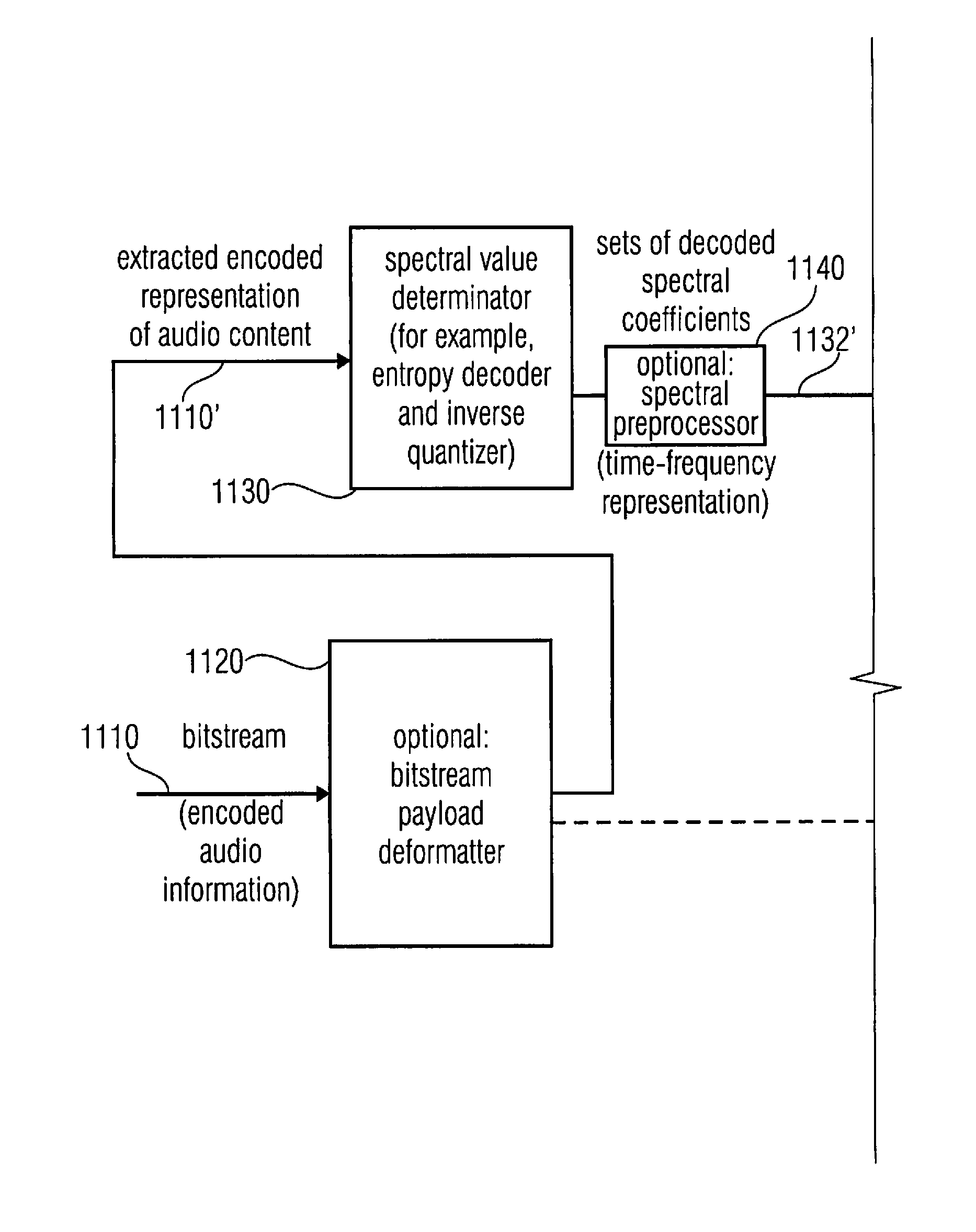
[0019]This multi-mode audio signal decoder is based on the finding that efficient transitions between portions of the audio content encoded in different modes can be obtained by performing a spectral shaping in the frequency domain, i.e., a spectral shaping of sets of decoded spectral coefficients, both for portions of the audio content encoded in the frequency-domain mode and for portions of the audio content encoded in the linear-prediction mode. By doing so, a time-domain representation obtained on the basis of a spectrally shaped set of decoded spectral coefficients for a portion of the audio content encoded in the linear-prediction mode is “in the same domain” (for example, are output values of frequency-domain-to-time-domain transforms of the same transform type) as a time domain representation obtained on the basis of a spectrally shaped set of decoded spectral coefficients for a portion of the audio content encoded in the frequency-domain mode. Thus, the time-domain representations of a portion of the audio content encoded in the linear prediction mode and of a portion of the audio content encoded in the frequency-domain mode can be combined efficiently and without inacceptable artifacts. For example, aliasing cancellation characteristics of typical frequency-domain-to-time-domain converters can be exploited by frequency-domain-to-time-domain converting signals, which are in the same domain (for example, both represent an audio content in an audio content domain). Thus, good quality transitions can be obtained between portions of the audio content encoded in different modes without needing a substantial amount of bit rate for allowing such transitions.
[0042]In an embodiment, the multi-mode audio signal encoder is configured to use the linear-prediction-domain parameters associated with the linear-prediction mode start frame in order to initialize an algebraic-code-excited-linear prediction mode encoder for encoding at least a portion of the combined linear-prediction mode / algebraic-code-excited-linear-prediction mode frame following the linear-prediction mode start frame. Accordingly, the linear-prediction-domain parameters, which are obtained for the linear-prediction mode start frame, and which are also encoded in a bit stream representing the audio content, are re-used for the encoding of a subsequent audio frame, in which the ACELP-mode is used. This increases the efficiency of the encoding and also allows for an efficient decoding without additional ACELP initialization side information.

Problems solved by technology

Moreover, it has been found that the performance of frequency-domain based audio coders is not optimal for audio contents comprising speech.
However, it has been found that it is difficult to transition between frames encoded in different domains without sacrificing a significant amount of bit rate.

Method used


Image

  • Multi-mode audio signal decoder, multi-mode audio signal encoder, methods and computer program using a linear-prediction-coding based noise shaping
  • Multi-mode audio signal decoder, multi-mode audio signal encoder, methods and computer program using a linear-prediction-coding based noise shaping
  • Multi-mode audio signal decoder, multi-mode audio signal encoder, methods and computer program using a linear-prediction-coding based noise shaping

Examples


Embodiment Construction

1. Audio Signal Encoder According to FIG. 1

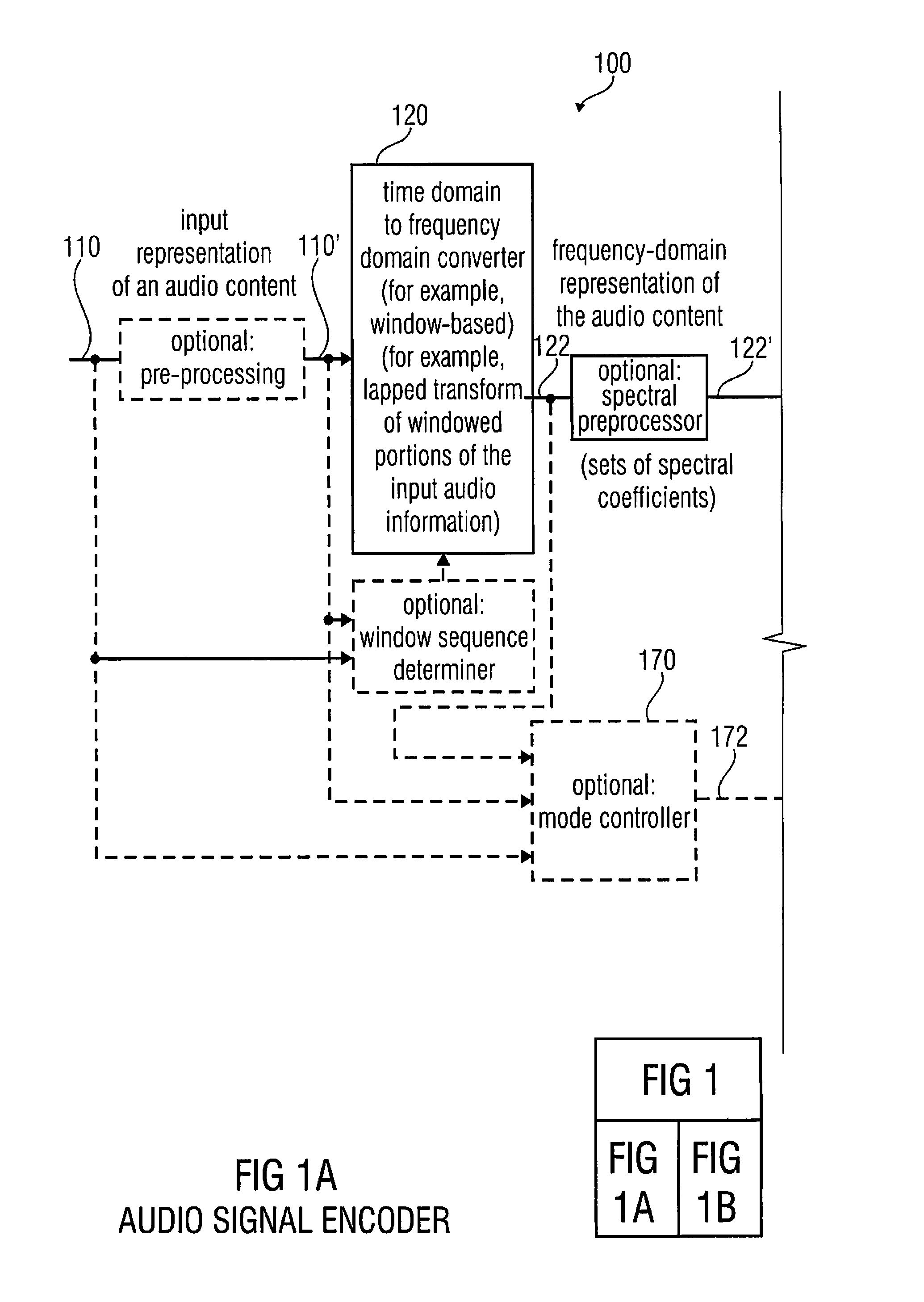
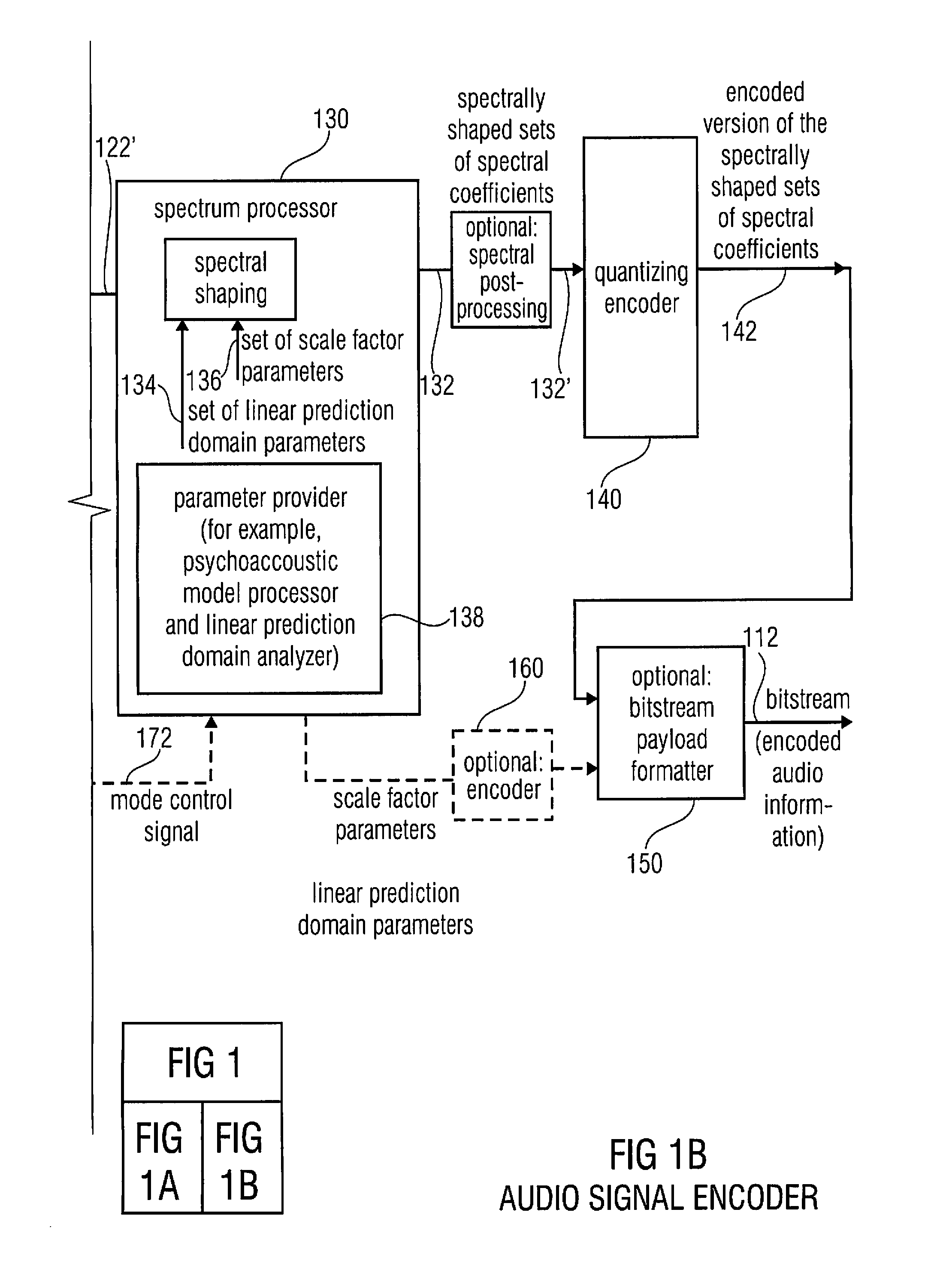
[0069]In the following, an audio signal encoder according to an embodiment of the invention will be discussed taking reference to FIG. 1, which shows a block schematic diagram of such a multi-mode audio signal encoder 100. The multi-mode audio signal encoder 100 is sometimes also briefly designated as an audio encoder.

[0070]The audio encoder 100 is configured to receive an input representation 110 of an audio content, which input representation 100 is typically a time-domain representation. The audio encoder 100 provides, on the basis thereof, an encoded representation of the audio content. For example, the audio encoder 100 provides a bitstream 112, which is an encoded audio representation.

[0071]The audio encoder 100 comprises a time-domain-to-frequency-domain converter 120, which is configured to receive the input representation 110 of the audio content, or a pre-processed version 110′ thereof. The time-domain-to-frequency-domain converte...


PUM


Abstract

A multi-mode audio signal decoder has a spectral value determinator to obtain sets of decoded spectral coefficients for a plurality of portions of an audio content and a spectrum processor configured to apply a spectral shaping to a set of spectral coefficients in dependence on a set of linear-prediction-domain parameters for a portion of the audio content encoded in a linear-prediction mode, and in dependence on a set of scale factor parameters for a portion of the audio content encoded in a frequency-domain mode. The audio signal decoder has a frequency-domain-to-time-domain converter configured to obtain a time-domain audio representation on the basis of a spectrally-shaped set of decoded spectral coefficients for a portion of the audio content encoded in the linear-prediction mode and for a portion of the audio content encoded in the frequency domain mode. An audio signal encoder is also described.

Description

CROSS-REFERENCE TO RELATED APPLICATIONS[0001]This application is a continuation of copending International Application No. PCT / EP2010 / 064917, filed Oct. 6, 2010, which is incorporated herein by reference in its entirety, and additionally claims priority from U.S. Application No. US 61 / 249,774 filed Oct. 8, 2009, which is incorporated herein by reference in its entirety.BACKGROUND OF THE INVENTION[0002]Embodiments according to the present invention are related to a multi-mode audio signal decoder for providing a decoded representation of an audio content on the basis of an encoded representation of the audio content.[0003]Further embodiments according to the invention are related to a multi-mode audio signal encoder for providing an encoded representation of an audio content on the basis of an input representation of the audio content.[0004]Further embodiments according to the invention are related to a method for providing a decoded representation of an audio content on the basis of...

Claims


Application Information

Patent Timeline
Patent Type & Authority Applications(United States)
IPC IPC(8): G10L19/00
CPCG10L19/20G10L19/022G10L19/02
Inventor NEUENDORF, MAXFUCHS, GUILLAUMERETTELBACH, NIKOLAUSBAECKSTROEM, TOMLECOMTE, JEREMIEHERRE, JUERGEN
Owner FRAUNHOFER GESELLSCHAFT ZUR FOERDERUNG DER ANGEWANDTEN FORSCHUNG EV
Learn More