
Apparatus for polishing using improved plate supports

a technology of plate support and polishing plate, which is applied in the direction of grinding machine components, manufacturing tools, lapping machines, etc., can solve the problems of unsatisfactory polishing/grinding techniques, unsatisfactory known techniques, and often minor non-planarities of polishing plates

Inactive Publication Date: 2001-01-02
SPEEDFAM IPEC
View PDF14 Cites 38 Cited by
  • Summary
  • Abstract
  • Description
  • Claims
  • Application Information

AI Technical Summary

Benefits of technology

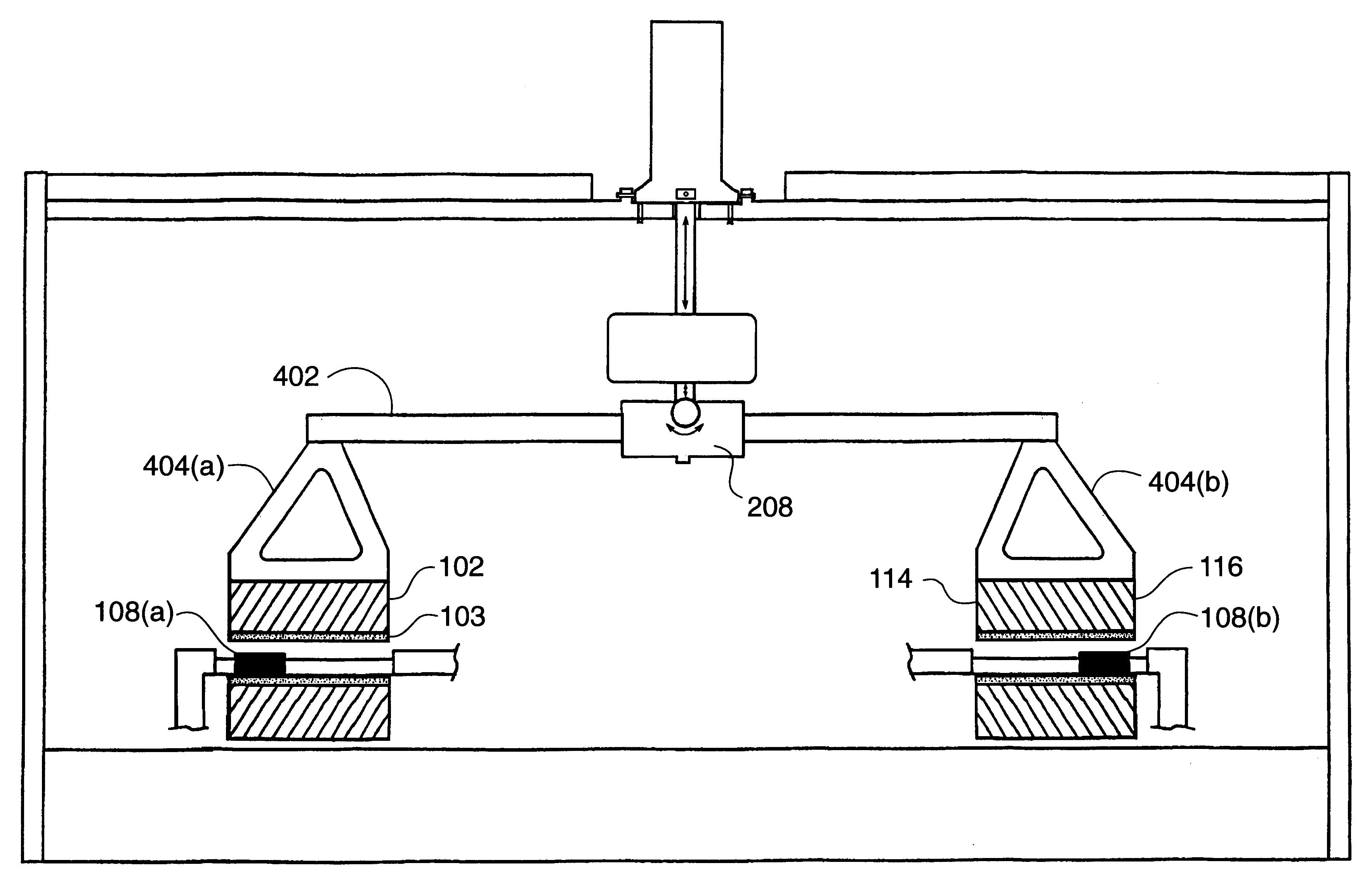
In accordance with one aspect of the present invention, a preferred support reduces radial stress variations arising from non-optimum positioning of support points with respect to the inner and outer diameters of the polishing surface.
In accordance with another aspect of the present invention, a preferred support reduces radial stress variations arising from the effects of increasing applied pressure; that is, the stress distribution at the workpiece surface remains substantially constant as applied pressure is increased.

Problems solved by technology

Presently known polishing / grinding techniques are unsatisfactory in several regards.
Presently known techniques are also unsatisfactory in that, due to manufacturing limitations, polishing plates often exhibit minor non-planarities.
Chemical mechanical planarization techniques are thus needed which reduce variation in material removal rates resulting from force variations across the polishing surface introduced as a result of non-optimum plate supports.

Method used


Image

  • Apparatus for polishing using improved plate supports
  • Apparatus for polishing using improved plate supports
  • Apparatus for polishing using improved plate supports

Examples


Embodiment Construction

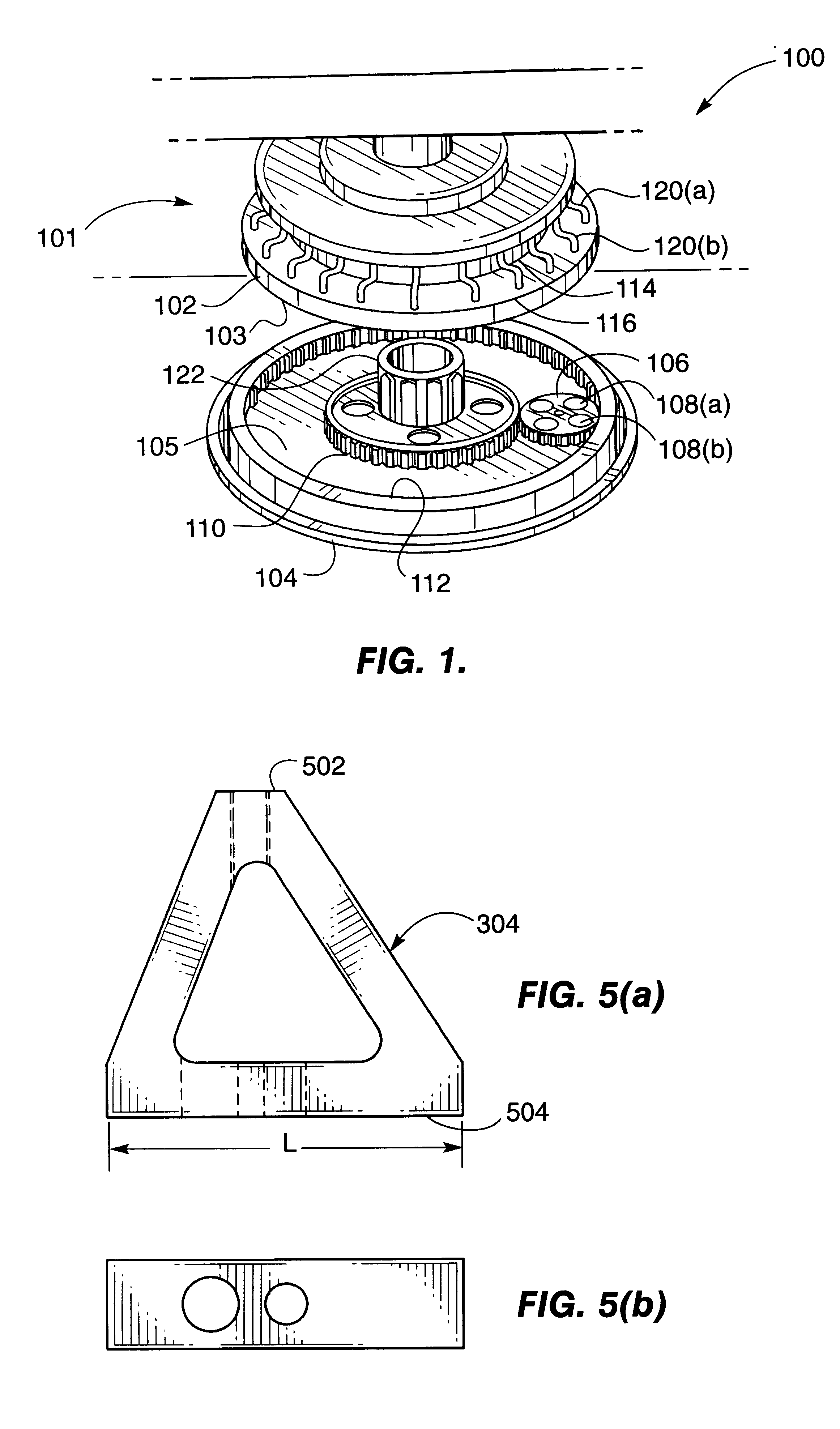
With reference to FIG. 1, an exemplary polishing apparatus 100 useful in illustrating the present invention will now be described. As a preliminary matter, the terms "polishing" and "polisher" as used herein embrace a wide range of both wet and dry planarization techniques, for example chemical-mechanical polishing, lapping, grinding honing slurry polishing, and chemical-mechanical planarization (CMP). As the primary goal of the present invention is to enhance material removal rate uniformity by providing substantially equal pressure over a workpiece or workpieces, the present invention may be advantageously employed in a variety of such contexts.

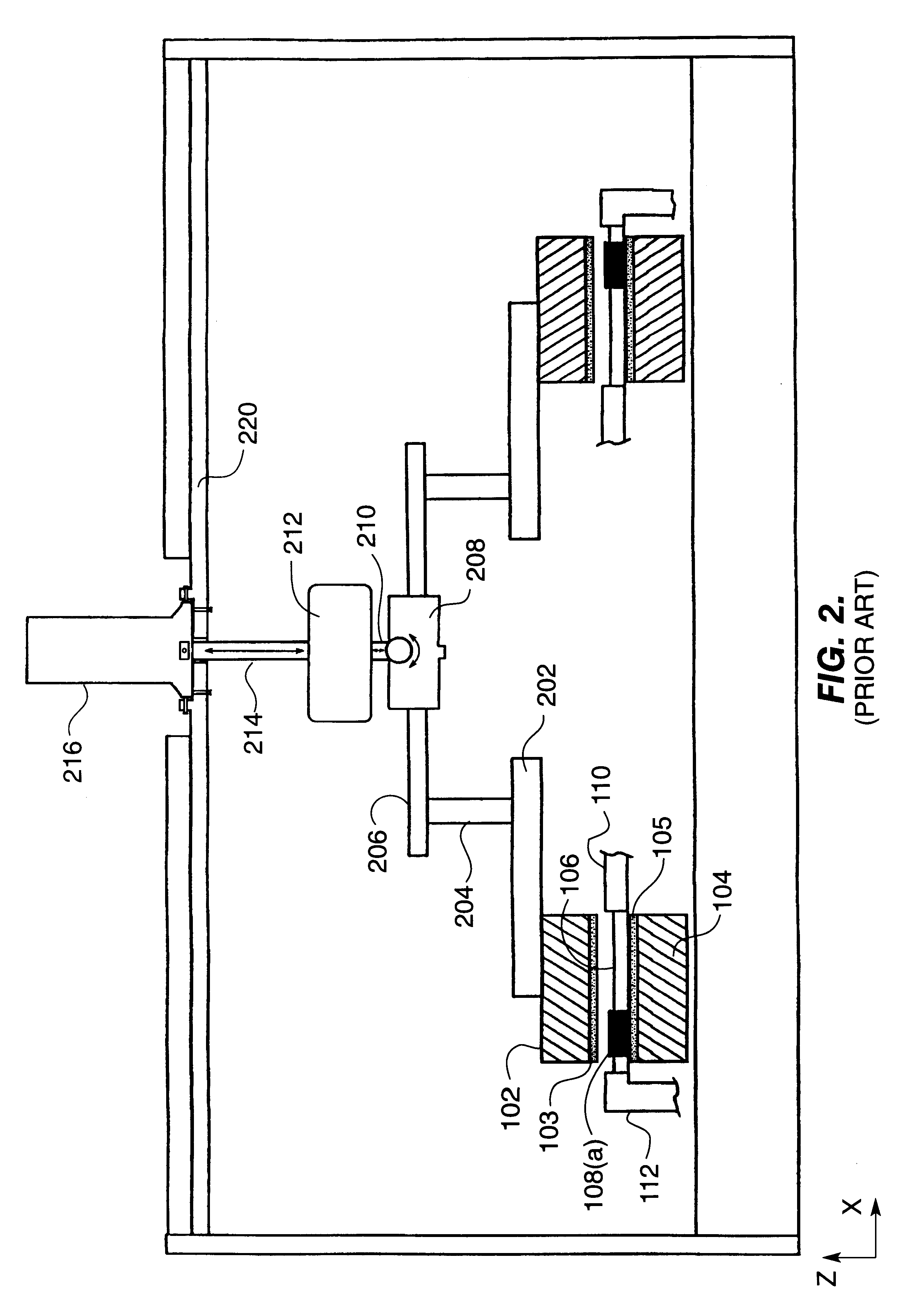
An exemplary double-side polishing apparatus 100 useful in illustrating the present invention comprises a top plate 102, a plurality of slurry supply lines 120, a bottom plate 104, and a carrier 106 for housing at least one workpiece 108. The bottom surface (not shown) of top plate 202 and the top surface of bottom plate 104 comprise a suit...


PUM


Abstract

A set of supports are advantageously disposed on a top plate having a polishing surface useful for polishing workpieces, thereby applying substantially uniform pressure to the top plate. In a preferred embodiment, the supports are non-isosceles triangular elements distributed evenly at 45 degree increments around a ring-shaped top plate. This structure effectively compensates for radial stress variations arising from non-optimum positioning of support points with respect to the inner and outer diameters of the polishing surface.

Description

The present invention relates, generally, to techniques for polishing workpieces and, more particularly, to the use of improved plate support structures to increase pressure uniformity at the workpiece surface.BACKGROUND ART AND TECHNICAL PROBLEMSPolishing technology has been largely driven by the need for exceptionally smooth and planarized surfaces on high-tech materials and components such as magnetic disks, semiconductors, and the like. In the case of semiconductor wafers, for example, polishing techniques are employed not just for polishing and planarizing the bulk wafer, but also for planarization of those layers which comprise the active circuitry; e.g., conductor metals, passivation, and inter-layer dielectrics.In a paradigmatic polishing operation, a platen / polishing-pad assembly is employed in conjunction with a slurry, for example a water-based slurry comprising colloidal silica particles. When pressure is applied between the polishing pad (e.g., a polyurethane pad) and t...

Claims


Application Information

Patent Timeline
IPC IPC(8): B24B37/04B24B41/00B24B41/04B24B37/08
CPCB24B37/08B24B41/042
Inventor MCJUNKEN, BOB
Owner SPEEDFAM IPEC
Learn More