Sorbent-based gas storage and delivery system for dispensing of high-purity gas, and apparatus and process for manufacturing semiconductor devices, products and precursor structures utilizing same

Inactive Publication Date: 2000-10-17
ENTEGRIS INC
View PDF59 Cites 161 Cited by
  • Summary
  • Abstract
  • Description
  • Claims
  • Application Information

AI Technical Summary

Benefits of technology

(A) scavengers including a support having associated therewith, but not covalently bonded thereto, a compound which in the presence of such contaminant prov

Problems solved by technology

The method disclosed in the Knollmueller patent is disadvantageous in that it requires the provision of heating means for the zeolite material, which must be constructed and arranged to heat the zeolite to sufficient temperature to desorb the previously sorbed arsine from the zeolite in the desired quantity.
The use of a heating jacket or other means exterior to the vessel holding the arsine-bearing zeolite is problematic in that the vessel typically has a significant heat capacity, and therefore introduces a significant lag time to the dispensing operation.
Further, heating of arsine causes it to decompose, resulting in the formation of hydrogen gas, which introduces an explosive hazard into the process system.
Additionally, such thermally-mediated decomposition of arsine effects substantial increase in gas pressure in the process system, which may be extremely disadvantageous from the standpoint of system life and operating efficiency.
The provision of interiorly disposed heating coil or other heating elements in the zeolite bed itself is problematic since it is difficult with such means to uniformly heat the zeolite bed to achieve the desired uniformity of arsine gas release.
The use of heated carrier gas streams passed through the bed of zeolite in its containment vessel may overcome the foregoing deficiencies, but the temperatures necessary to achieve the heated carrier gas desorption of arsine may be undesirably high or otherwise unsuitable for the end use of the arsine gas, so that cooling or other treatment is required to condition the dispensed gas for ultimate use.
Heating means may be employed to augment the desorption process, but as mentioned above, heating entails various disadvantages for the sorption / desorption system, and it therefore is preferred to operate the Tom et al. system with the desorption being carried out at least partially by pressure differential-mediated release of the sorbate gas from the sorbent medium.
Conventional high pressure gas cylinders are susceptible to leakage from damaged or malfunctioning regulator assemblies, as well as to rupture and unwanted bulk release of gas from the cylinder if the internal gas pressure in the cylinder exceeds permissible limits.
Many of the gases or high vapor pressure liquids used in these cleans are hazardous, exhibiting one or more of the following properties: toxicity, flammability, pyrophoricity and / or adverse impact on the ozone layer (by so-called global warming gases).
In addition to the aforementioned cleaning reagents, many other process gases used in the manufacture of semiconductors are hazardous and exhibit one or more of the following properties: toxicity, flammability or pyrophoricity.
In particular, chemical vapor deposition processes (CVD) are carried out with gaseous or liquid feed stocks which in many instances are associated with significant health and safety issues.
A serious problem with storage and dispensing systems of the general type described in U.S. Pat. No. 5,518,528 is decomposition of the stored gas, such as hydride gas species.
Hydrogen gas is flammable and has an associated safety risk, as well as increasing the pressure of the stored gas beyond desired levels (of atmospheric or near-atmospheric pressure).

Method used


Image

  • Sorbent-based gas storage and delivery system for dispensing of high-purity gas, and apparatus and process for manufacturing semiconductor devices, products and precursor structures utilizing same
  • Sorbent-based gas storage and delivery system for dispensing of high-purity gas, and apparatus and process for manufacturing semiconductor devices, products and precursor structures utilizing same
  • Sorbent-based gas storage and delivery system for dispensing of high-purity gas, and apparatus and process for manufacturing semiconductor devices, products and precursor structures utilizing same

Examples


Embodiment Construction

The disclosures of the following U.S. patents and patent applications are hereby incorporated herein by reference in their entirety: U.S. Pat. No. 5,518,528 issued May 21, 1996; U.S. Pat. No. 5,704,965 issued Jan. 6, 1998; U.S. Pat. No. 5,704,967 issued Jan. 6, 1998; U.S. Pat. No. 5,707,424 issued Jan. 13, 1998; U.S. patent application Ser. No. 08 / 809,019 filed Apr. 11, 1997; and U.S. patent application Ser. No. 08 / 859,172 filed May 20, 1997; and U.S. patent application Ser. No. 09 / 002,278 filed Dec. 31, 1997.

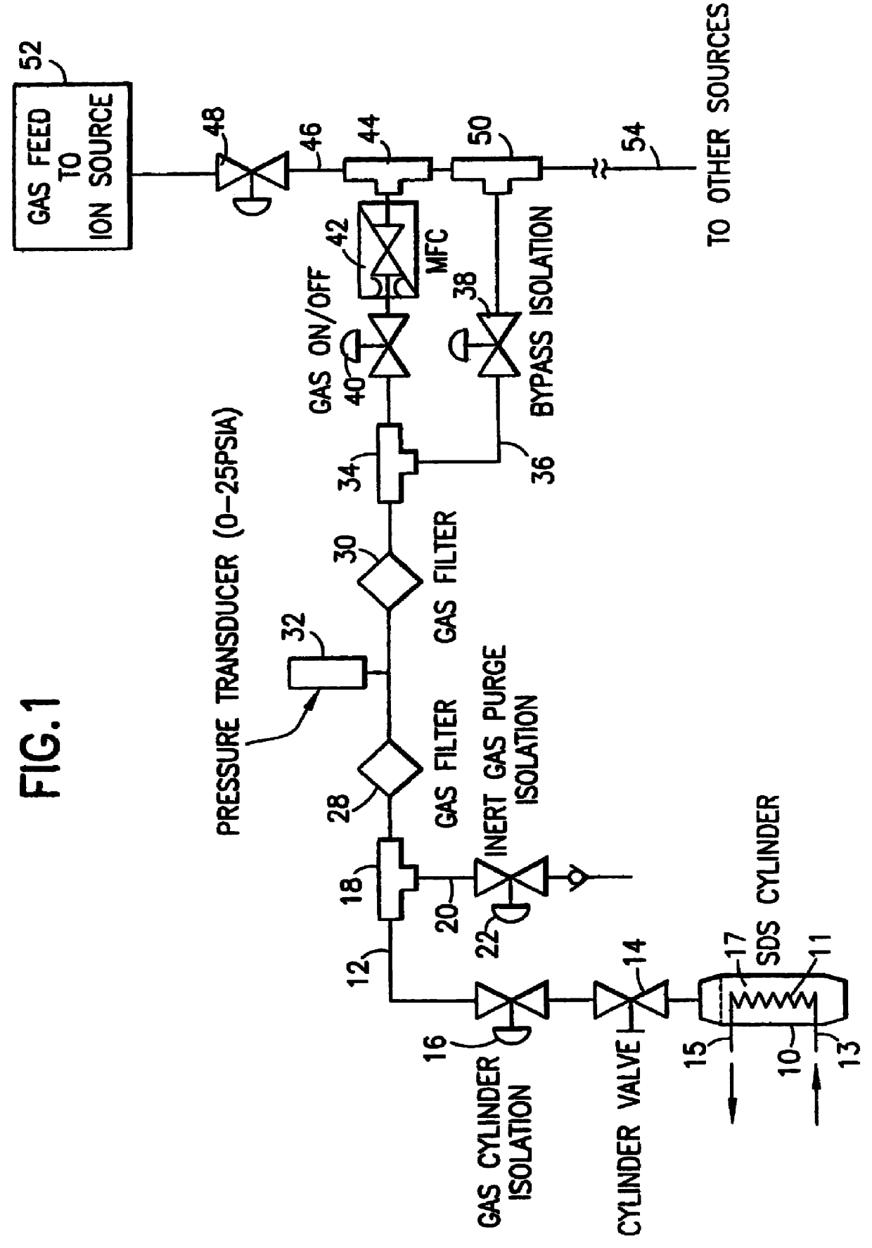
Referring now to the drawings, FIG. 1 is a schematic representation of a storage and delivery system according to one embodiment of the invention.

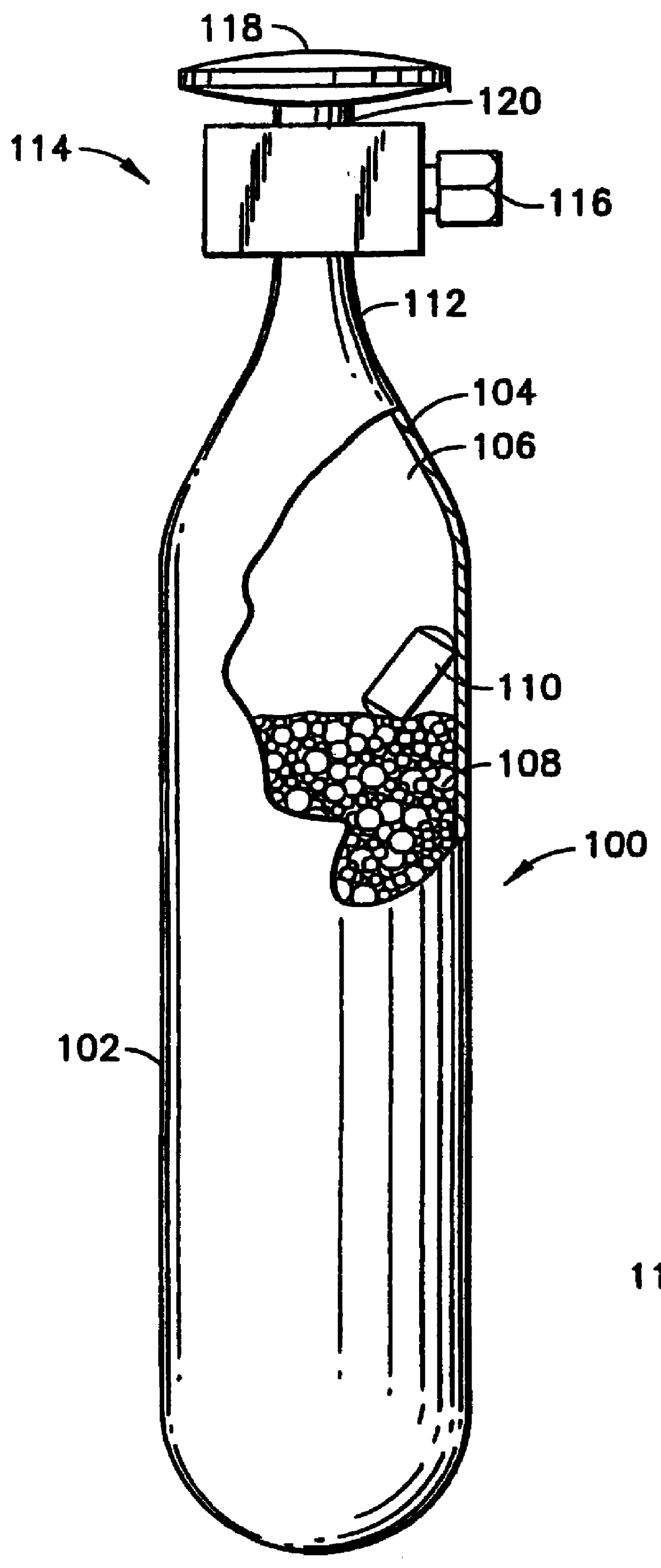
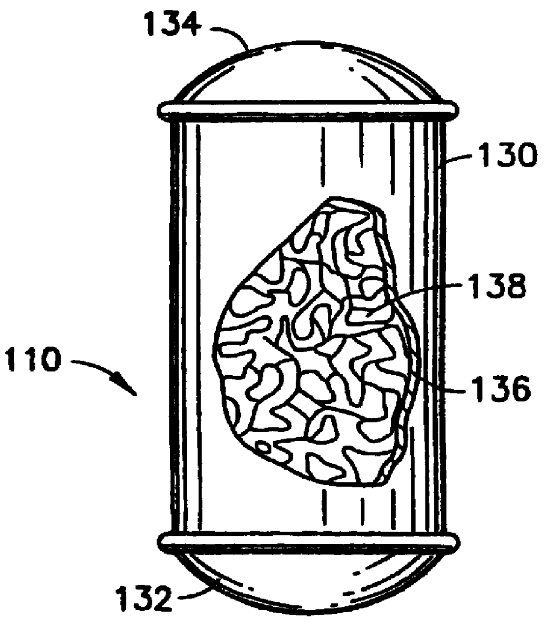
In the schematic storage and delivery system shown in FIG. 1, a gas storage cylinder 10 is provided which may be filled with a bed 17 of suitable physical adsorbent material, e.g., a bead activated carbon physical adsorbent medium or other suitable sorbent material having sorptive affinity for the gas to be stored in and subsequently ...


PUM

PropertyMeasurementUnit
Angleaaaaaaaaaa
Surface areaaaaaaaaaaa
Dissociation constantaaaaaaaaaa

Abstract

A sorbent-based gas storage and dispensing system, including a storage and dispensing vessel containing a solid-phase physical sorbent medium having a sorbate gas physically adsorbed thereon. A chemisorbent material is provided in the vessel to chemisorb the impurities for gas phase removal thereof in the storage and dispensing vessel. Desorbed sorbate gas is discharged from the storage and dispensing vessel by a dispensing assembly coupled to the vessel. The chemisorbent may be provided in a capsule including an impurity-permeable, but sorbate gas-impermeable membrane, and installed in the vessel at the time of sorbent material loading. Semiconductor manufacturing processes and products manufactured by such processes are described.

Description

1. Field of the InventionThis invention relates generally to storage and dispensing systems for the selective dispensing of a gas from a storage and dispensing vessel containing a physical sorbent medium, on which the gas has been sorbed, and from which the gas is desorbed in the dispensing operation. The invention further relates to semiconductor manufacturing systems and processes utilizing such storage and dispensing systems for reagent delivery, to electronic device structures obtained by such semiconductor manufacturing processes, and to end use products including such electronic device structures.2. Description of the Related ArtIn a wide variety of industrial processes and applications, there is a need for a reliable source of process fluid(s) which is compact, portable, and available to supply the process fluid(s) on demand. Such industrial processes and applications include semiconductor manufacturing, ion implantation, manufacture of flat panel displays, medical treatment,...

Claims


Application Information

Patent Timeline
IPC IPC(8): F17C11/00B01D53/04B01D53/22B01D53/34
CPCB01D53/0446B01D53/34F17C11/00B01D53/229Y10S95/901B01D2253/102B01D2253/104B01D2253/108B01D2253/202B01D2256/26B01D2258/0216B01D2259/4525F17C2223/0123F17C2270/0518H01J2237/006H01J2237/31701Y10S95/902B01D53/04
Inventor HULTQUIST, STEVEN J.TOM, GLENN M.KIRLIN, PETER S.MCMANUS, JAMES V.
Owner ENTEGRIS INC
Why Eureka
Try Eureka