Kneading rotor, kneading machine, method for kneading rubber material, and method for manufacturing kneading rotor
a technology of kneading rotor and kneading rubber, which is applied in the field of kneading rotor, kneading machine, method for kneading rubber material, and method for manufacturing kneading rotor, which can solve the problems of corroding the base, unfavorable human health, and high cost of stellite alloy
- Summary
- Abstract
- Description
- Claims
- Application Information
AI Technical Summary
Benefits of technology
Problems solved by technology
Method used
Image

Examples
first embodiment
Kneading Rotor
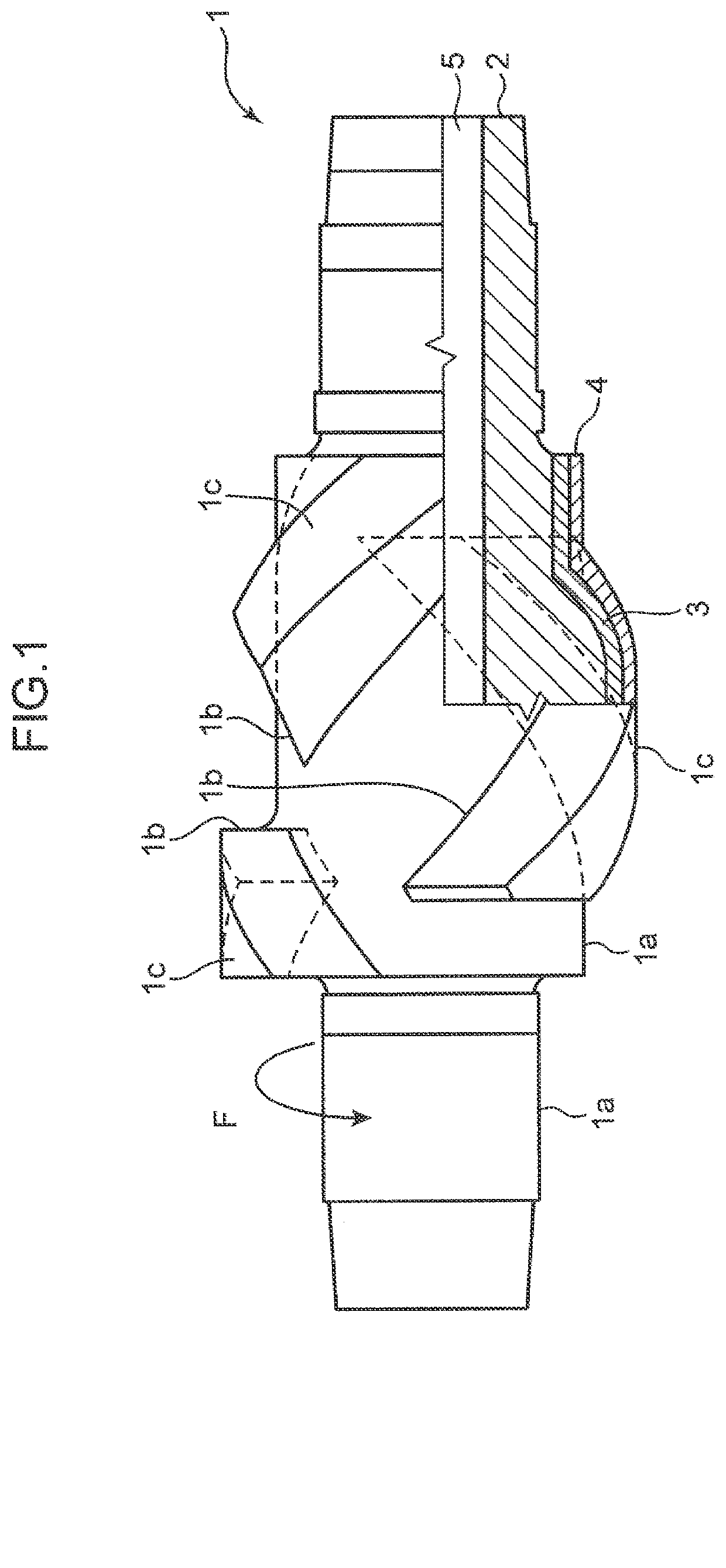
[0014]FIG. 1 is a partial cross-sectional view of a kneading rotor according to the present embodiment. The kneading rotor 1 is a kneading rotor for a kneading machine and, as illustrated in a cross-sectional portion of FIG. 1, has a base 2, a padded layer 3 provided on at least part of a surface of the base 2, and a hard chromium plated layer 4 provided on at least part of a surface of the padded layer 3.
[0015]The base 2 is made of carbon steel or alloy steel for machine structure, and has a portion constituting a shaft portion 1a and a kneading blade 1b. As the carbon steel constituting the base 2, common carbon steel can be used.
[0016]Carbon steel and alloy steel for machine structure are inexpensive as compared with other metal materials such as stainless steel, and are superior in strength and toughness. When a rubber material is kneaded, a large force is applied to the kneading rotor 1 as compared with kneading of powder or the like. However, as a result of the u...
second embodiment
Kneading Rotor
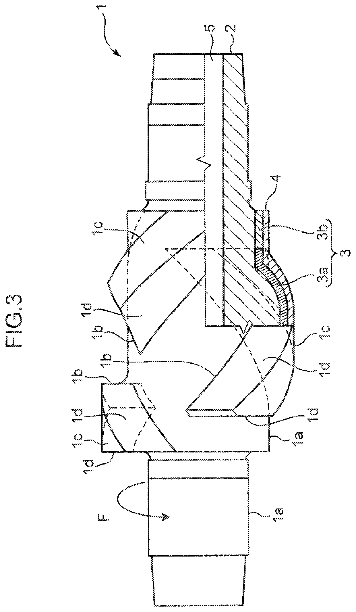
[0043]Next, a second embodiment of the present disclosure will be described. FIG. 3 is a partial cross-sectional view of a kneading rotor according to the present embodiment. In FIG. 3, constituent elements substantially the same as the constituent elements illustrated in FIG. 1 are denoted by the same reference numerals, and the description thereon will be omitted below.
[0044]The kneading rotor 1 according to the present embodiment differs from the kneading rotor according to the first embodiment in the configuration of the padded layer 3, and has the same configuration as the kneading rotor 1 according to the first embodiment except for this point. The padded layer 3 of the kneading rotor 1 according to the first embodiment is entirely made of austenitic stainless steel. In contrast, the padded layer 3 of the kneading rotor 1 according to the present embodiment has a first padded layer 3a made of Stellite on at least a tip portion 1c of a kneading blade 1b in a surfa...
examples
[0071]In Examples, corrosion resistance tests and abrasion resistance tests were performed using steel materials and metal materials having chemical component compositions (Nos. 1 to 4) shown in Table 2. The steel materials of No. 1 and No. 2 are austenitic stainless steel, and are examples of the present disclosure corresponding to the steel grade a shown in Table 1 described above. The steel material of No. 3 is martensitic stainless steel, and is a comparative example of the present disclosure. The metal material of No. 4 is an alloy containing cobalt as a main component (Stellite (registered trademark)), and is an example of the present disclosure. “0.00” shown in Table 1 indicates that it was less than the measurement limit. In Table 2, the values of hardness, tensile strength, and elongation of each steel material are also shown. Of the hardnesses of the steel material of No. 1, the value marked with * in the column of HRC hardness is HRB hardness.
TABLE 2Chemical component com...
PUM
| Property | Measurement | Unit |
|---|---|---|
| thickness | aaaaa | aaaaa |
| thickness | aaaaa | aaaaa |
| thickness | aaaaa | aaaaa |
Abstract
Description
Claims
Application Information
 - R&D
- Intellectual Property
- Life Sciences
- Materials
- Tech Scout
- Unparalleled Data Quality
- Higher Quality Content
- 60% Fewer Hallucinations
Browse by: Latest US Patents, China's latest patents, Technical Efficacy Thesaurus, Application Domain, Technology Topic, Popular Technical Reports.
© 2025 PatSnap. All rights reserved.Legal|Privacy policy|Modern Slavery Act Transparency Statement|Sitemap|About US| Contact US: help@patsnap.com