Backlight driving circuit and display device

Pending Publication Date: 2022-09-29
SHENZHEN CHINA STAR OPTOELECTRONICS SEMICON DISPLAY TECH CO LTD
View PDF2 Cites 0 Cited by
  • Summary
  • Abstract
  • Description
  • Claims
  • Application Information

AI Technical Summary

Benefits of technology

The present patent describes a display device that uses a backlight driving circuit. This circuit includes multiple field effect transistors and light-emitting diodes that are connected to a dimming control chip. Additionally, a voltage protection sub-circuit is included to prevent excessive temperatures and other reliability issues that can occur when the negative terminal voltage of a light-emitting diode is abnormal. The technical effect of this patent is to provide a more reliable and safe display device that can prevent malfunctions caused by abnormal voltages.

Problems solved by technology

However, due to disadvantages of the cold cathode fluorescent lamp backlight such as poor color reproduction, low luminous efficiency, high discharge voltage, poor discharge characteristics at low temperatures, and long time required for heating to reach a stable gray scale, backlight technology using light-emitting diodes has been developed currently.
However, the existing backlight driving circuit does not have a module for detecting a negative terminal voltage of the light-emitting diode.
Therefore, when the negative terminal voltage of the light-emitting diode is abnormal, a temperature of a triode in a dimming module for adjusting brightness of the light-emitting diode will rise, which affects reliability of the backlight driving circuit.
Therefore, how to prevent the occurrence of a phenomenon that the reliability of the backlight driving circuit is affected by the abnormality of the negative terminal voltage of the light emitting diode is a difficult problem that panel manufacturers all over the world are trying to overcome.

Method used


Image

  • Backlight driving circuit and display device
  • Backlight driving circuit and display device
  • Backlight driving circuit and display device

Examples


Embodiment Construction

[0058]Technical solutions in embodiments of the present disclosure will be clearly and completely described below in conjunction with drawings in the embodiments of the present disclosure. It is clear that the described embodiments are part of embodiments of the present disclosure, but not all embodiments. Based on the embodiments of the present disclosure, all other embodiments to those of ordinary skill in the premise of no creative efforts obtained, should be considered within the scope of protection of the present disclosure.

[0059]The following description provides various embodiments or examples for implementing various structures of the present disclosure. To simplify the description of the present disclosure, parts and settings of specific examples are described as follows. Certainly, they are only illustrative, and are not intended to limit the present disclosure. Further, reference numerals and reference letters may be repeated in different examples. This repetition is for ...


PUM


Abstract

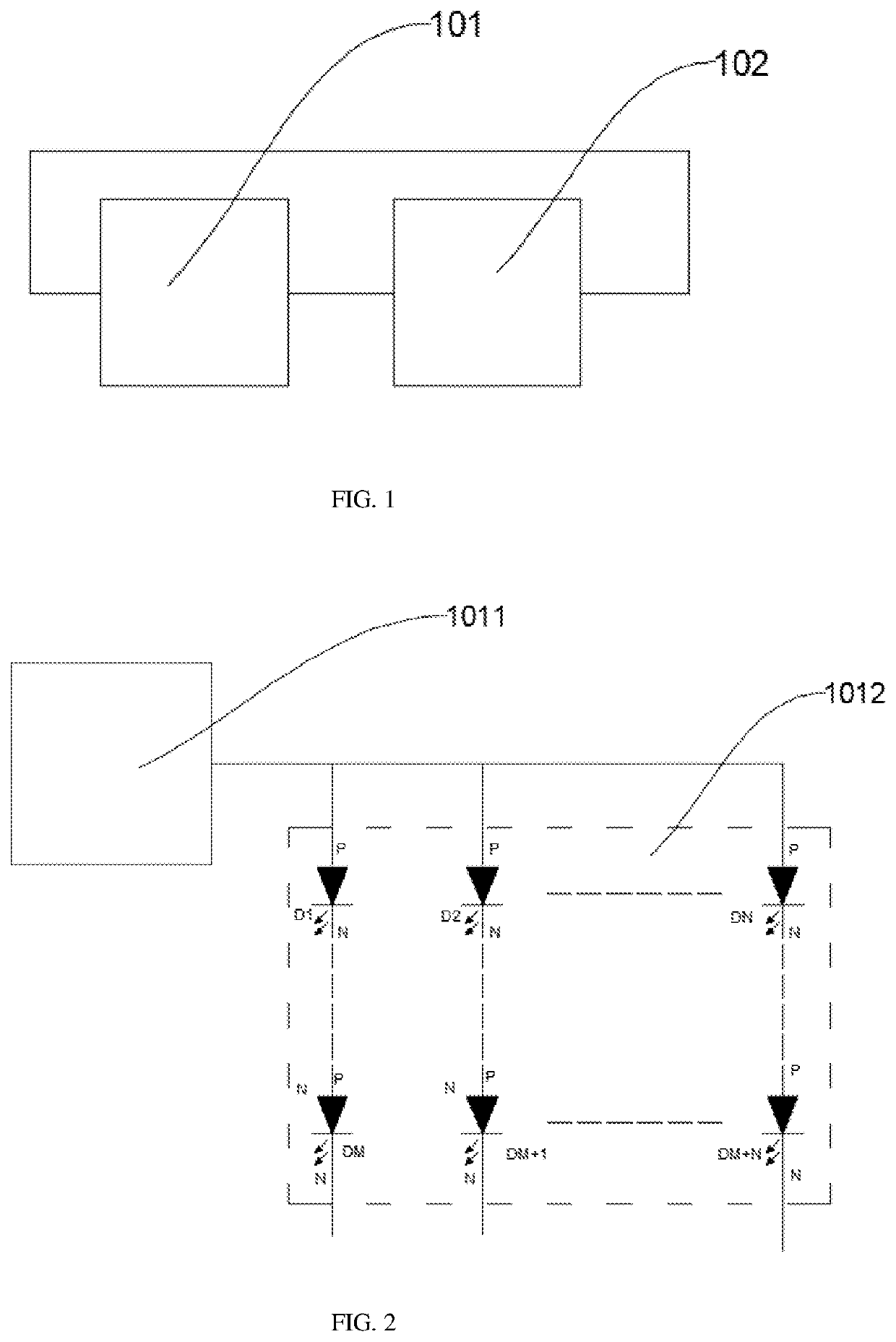
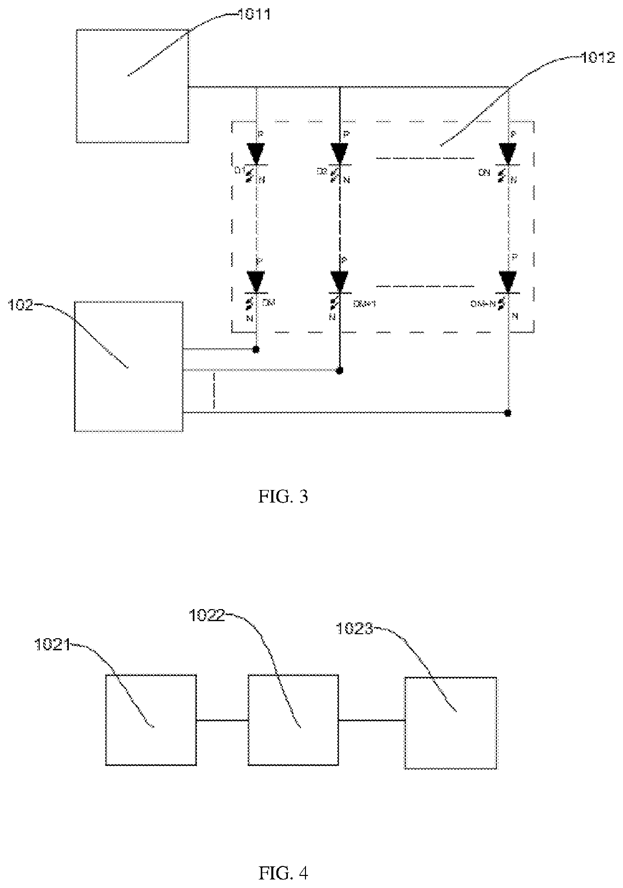
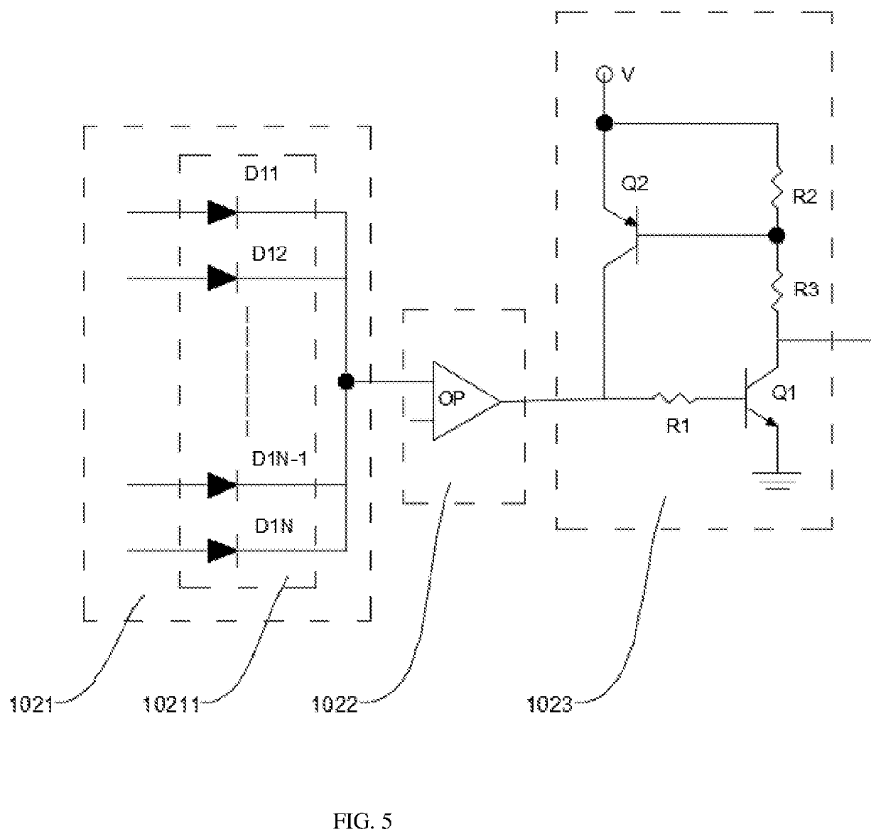
The present disclosure discloses a backlight driving circuit and a display device. The backlight driving circuit includes a power supply chip, light-emitting diodes connected to the power supply chip, and a voltage protection sub-circuit connected to both the light-emitting diodes and the power supply chip. By adding the voltage protection sub-circuit, when a negative terminal voltage of the light-emitting diode is abnormal, the voltage protection sub-circuit will output a feedback signal to the power supply chip to stop the power supply chip from working, thereby improving reliability of the backlight driving circuit.

Description

FIELD OF INVENTION[0001]The present disclosure relates to the field of display technology, specifically to a backlight driving circuit and a display device.BACKGROUND OF INVENTION[0002]With continuous advancement of technology, backlight technology of liquid crystal display devices has been continuously developed. A backlight of a traditional liquid crystal display device uses cold cathode fluorescent lamps. However, due to disadvantages of the cold cathode fluorescent lamp backlight such as poor color reproduction, low luminous efficiency, high discharge voltage, poor discharge characteristics at low temperatures, and long time required for heating to reach a stable gray scale, backlight technology using light-emitting diodes has been developed currently.[0003]In a light-emitting diode backlight, a special backlight driving circuit is required to provide a driving voltage for a light-emitting diode string to normally emit light. However, the existing backlight driving circuit does ...

Claims


Application Information

Patent Timeline
IPC IPC(8): H05B45/50H05B45/46H05B45/14
CPCH05B45/50H05B45/46H05B45/14G09G3/3406G09G3/36
Inventor TANG, SHIJIONG
Owner SHENZHEN CHINA STAR OPTOELECTRONICS SEMICON DISPLAY TECH CO LTD
Why Eureka
Try Eureka