
Subterranean fluid transport system and method of installation

a fluid transportation system and subterranean technology, applied in the direction of hose connection, borehole/well accessories, couplings, etc., can solve the problems of lack of early leak detection and warning systems, ineffective and impractical fluid transfer via tanker trucks, underground metal, plastic pipes and lay-flat hoses, etc., to reduce the installation time, reduce the cost of material, and remove the potential for failure

Active Publication Date: 2019-09-10
ROHLMEIER GRANT M +1
View PDF10 Cites 0 Cited by
  • Summary
  • Abstract
  • Description
  • Claims
  • Application Information

AI Technical Summary

Benefits of technology

The patent describes a new invention of a subterranean pipeline system that can handle large volumes of fluid and is faster to install and cheaper than traditional systems. This system includes a rigid outer surface pipe segment and a flexible inner sleeve that can be rated for the pressure required. The system also allows for the protection of the flexible inner sleeve in case of accidents and is quick to act in emergency situations. The use of a flexible inner sleeve also eliminates the need for welding, which reduces installation time and material costs. Overall, this invention provides a safer, more efficient and cost-effective way to transfer fluid underground.

Problems solved by technology

There are numerous conditions that make the transfer of fluid via tanker trucks, underground metal, plastic pipes and lay-flat hose inefficient and impractical.
Furthermore for the vast majority of installations there is lack of early leak detection and warning systems to warn workers in construction, farming or other industries that dig, bore, plow or move earth that a subterranean fluid transfer line is present.
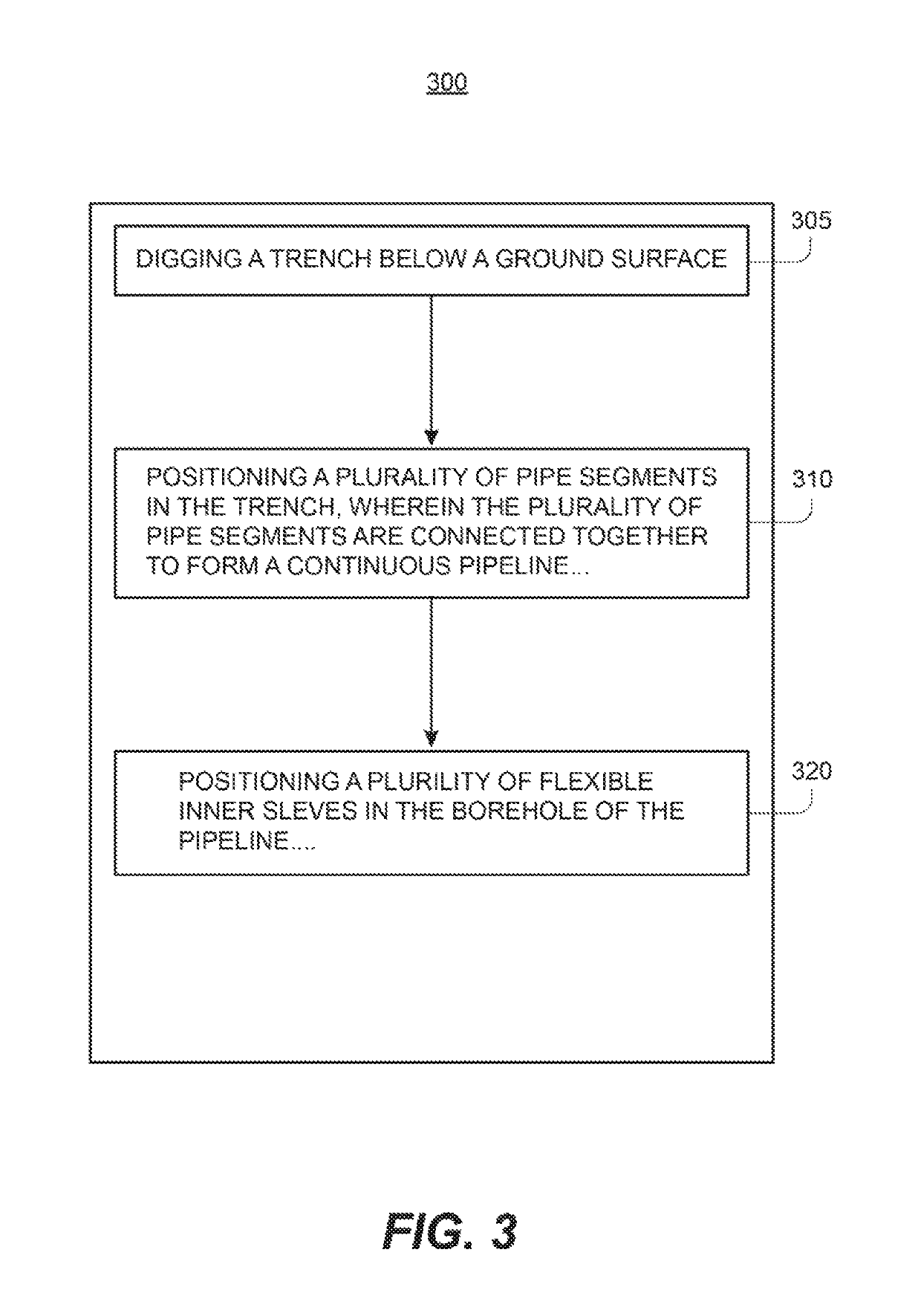
It is not practical to bury flexible hoses and pipes below a ground surface because such flexible pipes and hoses cannot be buried pressurized and if buried in a de-pressurized state the weight of the ground and soil above prevents such traditional flexible pipes and hoses from properly functioning as designed.

Method used


Image

  • Subterranean fluid transport system and method of installation
  • Subterranean fluid transport system and method of installation
  • Subterranean fluid transport system and method of installation

Examples


Embodiment Construction

[0019]Before explaining at least one embodiment of the inventive concepts disclosed herein in detail, it is to be understood that the inventive concepts are not limited in their application to the details of construction and the arrangements of the components or steps or methodologies set forth in the following description or illustrated in the drawings. The inventive concepts disclosed herein are capable of other embodiments or of being practiced or carried out in various ways. Also, it is to be understood that the phraseology and terminology employed herein is for the purpose of description and should not be regarded as limiting the inventive concepts claimed herein in any way.

[0020]In the following detailed description of embodiments of the inventive concepts, numerous specific details are set forth in order to provide a more thorough understanding of the inventive concepts. However, it will be apparent to one of ordinary skill in the art that the inventive concepts within the di...


PUM


Abstract

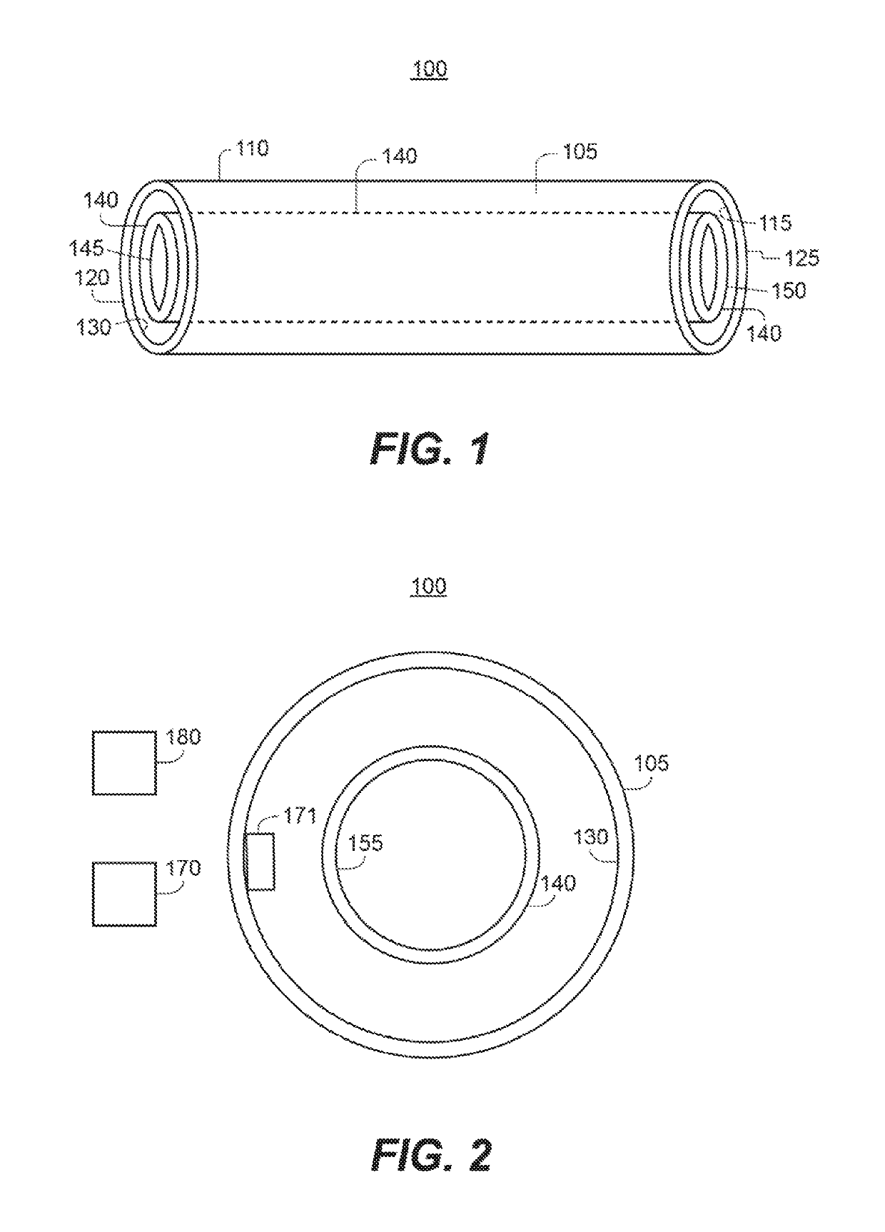
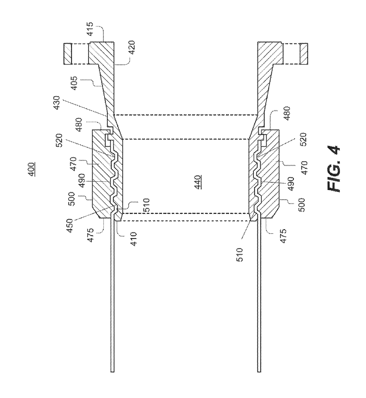
A subterranean fluid transport system, flange assembly and method of installation is disclosed. In some embodiments, the subterranean fluid transport system includes a pipe segment with a rigid outer surface and a flexible inner sleeve positioned within the borehole of the pipe segment. The flexible inner sleeve configured to expand and contract within the borehole of the pipe segment when fluid is transported therethrough.

Description

FIELD OF INVENTION[0001]The invention is in the technical field of subterranean fluid transport, delivery and transfer (whether in liquid or gaseous state) through a novel subterranean pipeline system and method of installation. The invention pertains generally to hoses, pipes, tubes, connections and flanges, of all manner of composition, the combination of which creates the subterranean pipeline system, flange assembly and method of installation described and claimed herein.BACKGROUND[0002]Throughout industry, in all manner of types and character, in all phases of each, be it agriculture, mining, energy and the like, large transfers of fluid both intermittent and continuous are required. Traditional fluid transfer systems can range from hundreds of feet to miles of differing diameters, compositions, combinations, design pressure ratings and configurations. There are numerous disadvantages in such traditional fluid transfer systems, including but not limited to, the lack of capacity...

Claims


Application Information

Patent Timeline
Patent Type & Authority Patents(United States)
IPC IPC(8): F16L9/18E21B43/00E02D29/00F16L1/028
CPCE02D29/10E21B43/00F16L1/028F16L9/18F16L1/11F16L11/10F16L23/024F16L33/28F16L2201/30
Inventor ROHLMEIER, GRANT M.JOHNSON, H. WARREN
Owner ROHLMEIER GRANT M
Learn More