Two step process for chemically recycling plastic waste

a technology of chemical recycling and plastic waste, applied in the direction of catalyst regeneration/reactivation, hydrocarbon oil treatment products, physical/chemical process catalysts, etc., can solve the problems of plastic recycling challenges, the us recycling rate is estimated to have dropped to only 4.4%, etc., and achieve the effect of simple feeding system

Active Publication Date: 2022-09-15
R PLUS JAPAN LTD
View PDF1 Cites 2 Cited by
  • Summary
  • Abstract
  • Description
  • Claims
  • Application Information

AI Technical Summary

Benefits of technology

[0014]There are many advantages of chemically recycling plastics by pyrolysis in a mechanically or gravitationally impelled reactor including: a mixture of any type of plastics is suitable, the plastic particles need not be ground to small size since the long residence time in the pyrolysis reactor or reactors ensures that the plastic pieces are heated to decomposition temperatures, the pyrolysis can be operated at high temperatures, vapor products can be readily separated from condensed phases within the pyrolysis reactor so that the vapors can be reacted in a catalytic reactor and the condensed phases can be regenerated and recycled or combusted, inorganic impurities in the plastic mixture are separated from the hydrocarbonaceous materials, and energy can be captured from the regeneration or combustion of the condensed phases for use in the process or for generating power.
[0015]Advantages of a two-step plastics upgrading process include: simple feeding system for vapors to the catalytic step, no danger of agglomeration in the fluidized bed causing defluidization or clumping in the bed, no need for good mixing of solid or molten plastic feed with catalyst particles, significantly narrower residence time distribution for pyrolysis gas in the catalytic reactor compared with the feed of solids, thus resulting in fewer heavy products, no carryover of plastic particles into the catalyst regenerator, fewer external impurities transferred into the catalytic reactor, no inorganic particles embedded in the polymer like fillers or additives are transferred into the catalytic reactor (fillers are usually alkaline (basic) and when reacting with the acidic catalyst cause its deactivation), heat is convectively supplied to the plastics without the use of steam that causes deactivation (dealumination) of the catalyst, and a greatly reduced need for additional fluidization gas rendering product recovery simpler and less costly.

Problems solved by technology

However, since China banned the import of waste plastics the recycle rate in the US is estimated to have dropped to only 4.4%.
Plastic recycling is challenging due to the chemical nature of the long chain organic polymers and low economic returns.

Method used


Image

  • Two step process for chemically recycling plastic waste
  • Two step process for chemically recycling plastic waste

Examples


examples 1 through 10

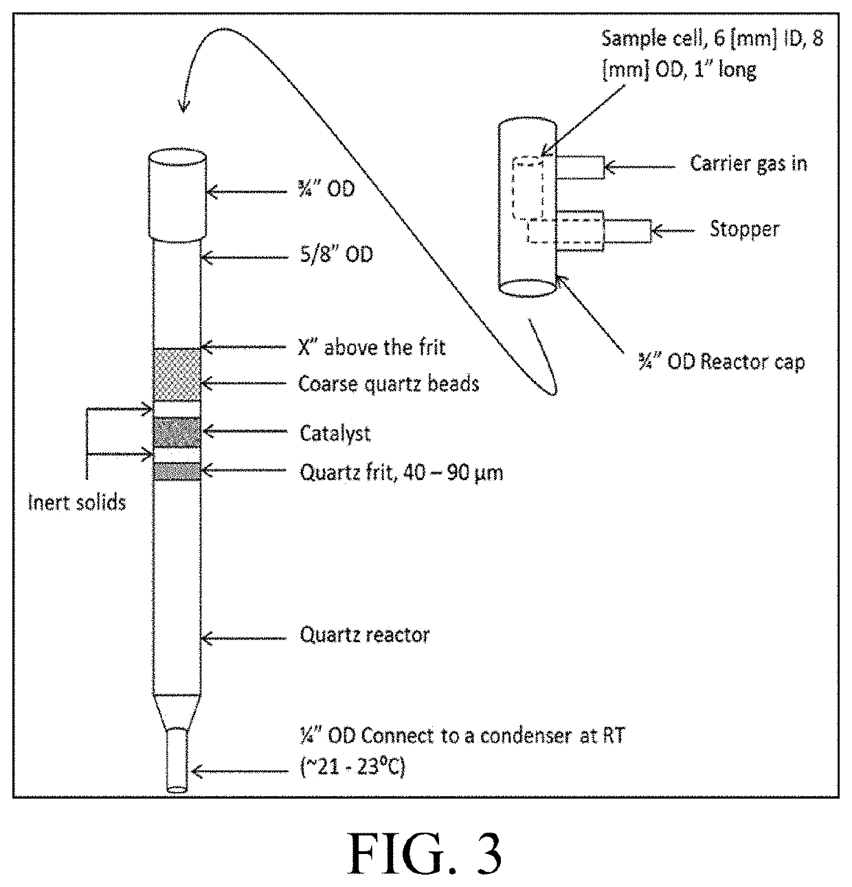
[0059]The drop-tube reactor for two-step chemical conversion of plastics comprises a quartz reactor tube (ACE Glass) containing a quartz frit (40-90 μm) fused into the center of the tube. FIG. 3 shows the configuration of the drop-tube reactor. A sample cell (10 mm OD, 8 mm ID, 25 mm length, quartz, made by TGP) is used to contain the feedstock using two pieces of quartz wool (TGP). As illustrated in FIG. 3, the sample cell was placed in a reactor cap (borosilicate, ACE Glass) and was held by a stopper (¼ inch (6 mm) aluminum rod, McMaster). The reactor cap and the quartz reactor were then assembled and installed onto the fixed-bed reactor system. The bottom of the reactor was connected to a condenser (borosilicate) filled with perforated stainless steel packing (ACE Glass) immersed in an ice-water bath (0° C.). A heating mantle was applied between the reactor bottom and the condenser top to prevent any condensation before the condenser. During the reaction, the heating mantle was s...


PUM

PropertyMeasurementUnit
temperatureaaaaaaaaaa
temperaturesaaaaaaaaaa

Abstract

A two-step process that includes a pyrolytic first step carried out in a mechanically or gravitationally impelled reactor and a catalytic fluid bed second step that upgrades the resulting vapor, for the conversion of waste plastics, polymers, and other waste materials to useful chemical and fuel products such as paraffins, olefins, and aromatics such as BTX is described.

Description

FIELD OF THE INVENTION[0001]This invention relates to the conversion of waste plastics, polymers, and other waste materials to useful chemical and fuel products such as paraffins, olefins, and aromatics such as BTX in a two-step process that includes a pyrolytic first step and a second step that upgrades the resulting vapor.INTRODUCTION[0002]In 2018, plastics generation in the United States was 38.5 million tons, which was 13.1 percent of MSW generation. World-wide over 350 million tons of plastics were produced. Plastic recycling recovers scrap or waste plastic and reprocesses the material into useful products. However, since China banned the import of waste plastics the recycle rate in the US is estimated to have dropped to only 4.4%.[0003]Plastic recycling is challenging due to the chemical nature of the long chain organic polymers and low economic returns. In addition, waste plastic materials often need sorting into the various plastic resin types, e.g. low density polyethylene ...

Claims


Application Information

Patent Timeline
Patent Type & Authority Applications(United States)
IPC IPC(8): C10B53/07C10B57/04B01J29/90B01J38/04C10G11/18C10G11/05
CPCC10B53/07C10B57/04B01J29/90B01J38/04C10G11/182C10G11/185C10G11/05C10G11/22C10G1/10C10G1/02C10G1/002C10G2400/30C10G2400/20C10G1/08C10G1/006
Inventor MLECZKO, LESLAWDASARATHY, RAGHAVACOIL, GREGCHENG, YU-TINGSCHMIDT, COLLINWHITING, JEFFCARABETTA, ROCCOMAZANEC, TERRY
Owner R PLUS JAPAN LTD
Why Eureka
Try Eureka