
Microscopy System and Method for Checking a Rotational Position of a Microscope Camera

a microscope camera and camera technology, applied in the field of microscope system and the field of checking the rotational position of the microscope camera, can solve the problems of loss of image information of analyzed sample areas

Pending Publication Date: 2022-07-28
CARL ZEISS MICROSCOPY GMBH
View PDF0 Cites 2 Cited by
  • Summary
  • Abstract
  • Description
  • Claims
  • Application Information

AI Technical Summary

Benefits of technology

The invention provides a microscopy system and method that allows for quick and accurate detection of the rotation of a microscope camera. By analyzing the orientation of the microscope camera relative to the sample stage or microscope stand, the system can determine the position of the microscope camera without the need for special calibration samples. The relationship between the orientations of the overview image and the microscope image can be determined using image analysis. The system can also capture multiple overview images and microscope images simultaneously to reduce light exposure and the translation paths of the sample stage can be short to minimize evaluation time. Additionally, the system can use segmentation masks to identify different objectives in the overview image and convert the overview image to a top view image for more precise stitching.

Problems solved by technology

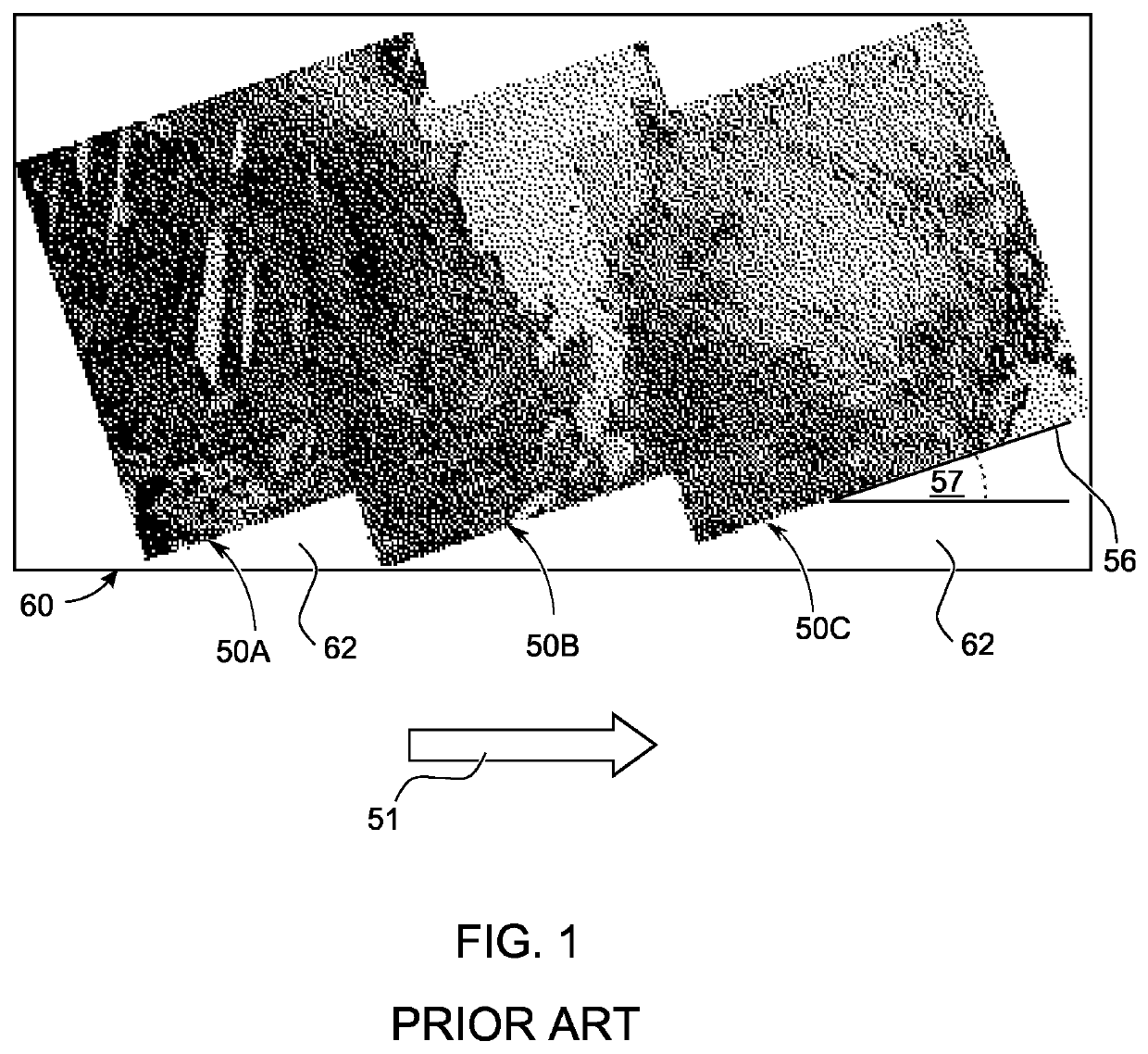
In other situations, however, an unsuitable rotational orientation can result in drawbacks, for example when a plurality of laterally overlapping microscope images are combined into an aggregate or panoramic image.
The aggregate image 60 can be cropped to remove the distracting blank image areas 62, but this results in the loss of image information of analyzed sample areas while the cropped aggregate image is potentially smaller than originally desired.
Not all samples are suitable for this purpose, however, so that a separate measurement using a calibration sample is often necessary before the actual analysis of a sample can begin.

Method used


Image

  • Microscopy System and Method for Checking a Rotational Position of a Microscope Camera
  • Microscopy System and Method for Checking a Rotational Position of a Microscope Camera
  • Microscopy System and Method for Checking a Rotational Position of a Microscope Camera

Examples


Embodiment Construction

[0066]Different example embodiments are described in the following with reference to the figures.

FIG. 2

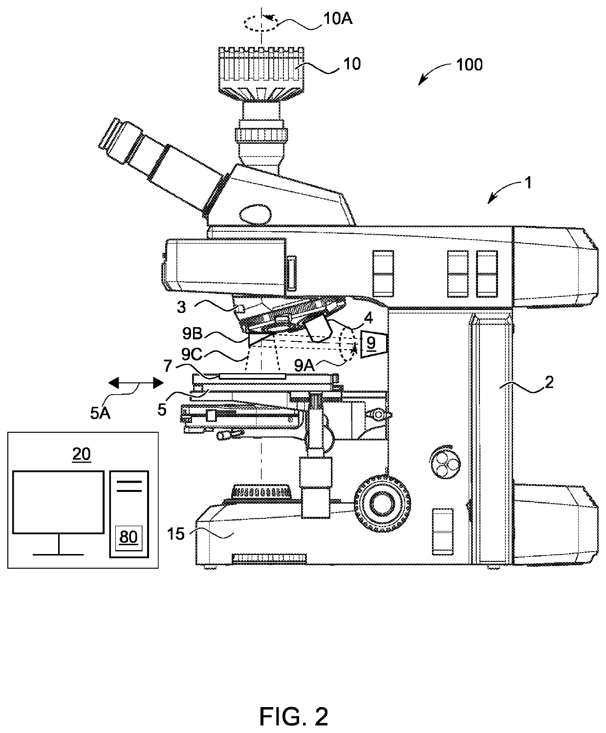
[0067]FIG. 2 shows an example embodiment of a microscopy system 100 according to the invention. The microscopy system 100 comprises a computing device 20 and a microscope 1, which is a light microscope in the illustrated example, but which can essentially be any type of microscope. The microscope 1 comprises a stand 2 via which further microscope components are supported. The latter can in particular include: an illumination device 15, an objective changer / revolver 3, on which an objective 4 is mounted in the illustrated example; a sample stage 5, on which a sample carrier 7 can be positioned, and a microscope camera 10. When the objective 4 has been rotated so as to be located in the light path of the microscope, the microscope camera 10 receives detection light from the sample area in order to capture a microscope image.

[0068]The microscope 1 also comprises an overview camera 9 f...


PUM


Abstract

In a method for checking the rotation of a microscope camera, an overview image is captured with an overview camera of a microscope, wherein a rotational orientation of the overview camera relative to a sample stage of the microscope is known. In addition, a microscope image is captured with a microscope camera of the microscope. A rotational orientation of the microscope camera relative to the sample stage is calculated based on a relative rotation between the microscope image and the overview image, wherein the relative rotation is established by means of image structures in the microscope image and the overview image and using the known rotational orientation of the overview camera relative to the sample stage.

Description

REFERENCE TO RELATED APPLICATIONS[0001]The current application claims the benefit of German Patent Application No. 10 2021 101 439.5, filed on 22 Jan. 2021, which is hereby incorporated by reference.FIELD OF THE DISCLOSURE[0002]The present disclosure relates to a microscopy system and to a method for checking a rotational position of a microscope camera.BACKGROUND OF THE DISCLOSURE[0003]Typical microscopy systems include, among other components, a camera (also referred to as a microscope camera in the following) and a sample stage by means of which a sample to be analyzed can be moved, in particular transversely to a viewing direction of the camera. The camera can be coupled to a microscope stand via an adapter, for example a C-mount adapter. The rotational orientation of the camera is consequently variable and thus not necessarily known. Different camera orientations can be expedient in some applications. For example, a user can select a rotational position by means of which an elo...

Claims


Application Information

Patent Timeline
IPC IPC(8): G02B21/36G06T7/73
CPCG02B21/361G06T2207/10056G06T7/73G02B21/244G02B21/365G06T7/74G06T7/60G06N3/088G06T2207/10061G06T2207/20081G06N3/045G06T2207/20084G06T2207/30244
Inventor AMTHOR, MANUELHAASE, DANIELOHRT, THOMAS
Owner CARL ZEISS MICROSCOPY GMBH
Learn More