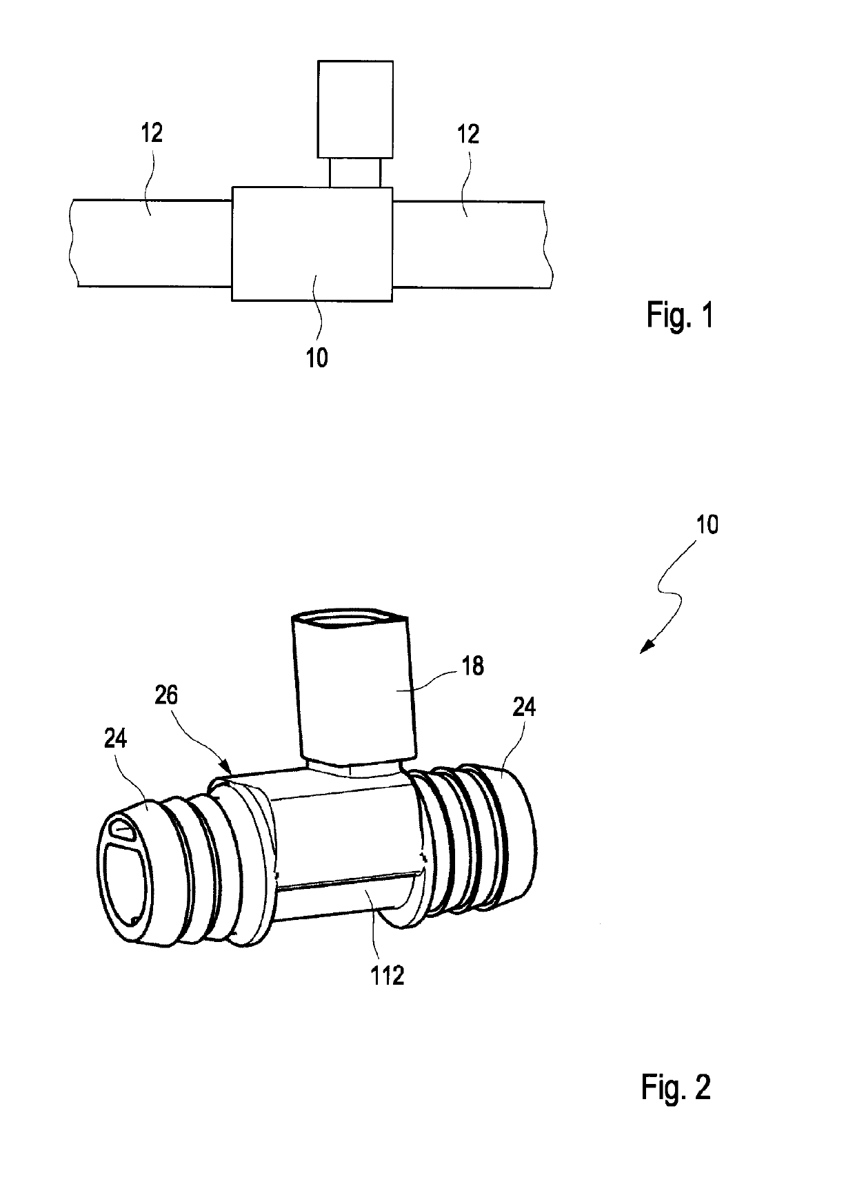
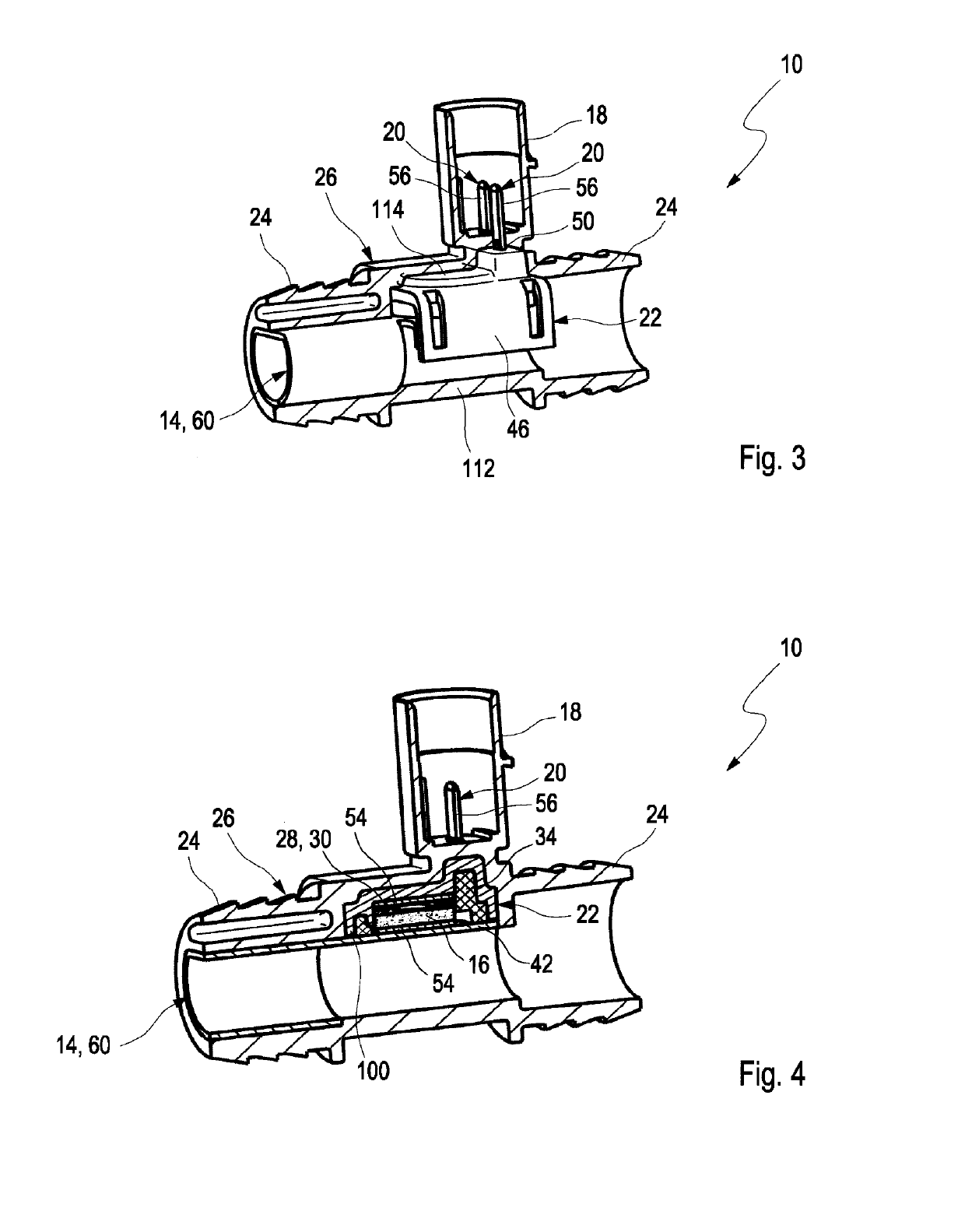
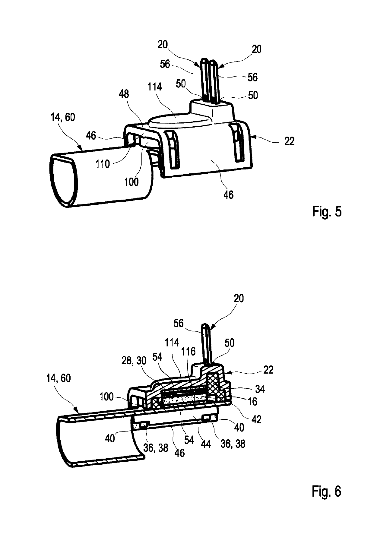
[0012]In other words, the invention concerns a heating device in which a heating element, in particular a PTC conductor that comprises contact elements for electrical contacting, is screwed on, riveted on, glued on, or attached in other ways to a heat-conductive pipe segment by means of a fastening element, in particular a plastic element. The plastic element presses the heating element onto the region of the pipe segment that is to be heated. Subsequently, the fastening element with the pressed-on heating element is embedded by injection molding in a plastic housing and is thereby encapsulated. Since the heating element is not directly embedded by injection molding into a plastic housing, but first is attached by the fastening element mechanically to the pipe segment, electrical contacting and defined attachment of the heating element on the heat-conductive pipe segment can be ensured independent of embedding by plastic injection molding. The plastic housing serves only as a protection against outer environmental influences and can provide gas-tight encapsulation. Moreover, the plastic housing forms the housing of the plug connection device wherein the contact elements which are connected immediately with the heating element may project into the plug connection device. Due to the attachment of the heating element on the pipe segment by means of a fastening element, the intermediate product can be electrically tested preliminarily and corrections without causing destruction can be performed before finally a plastic housing is injection-molded thereon. The fastening element secures the heating element on the region of the pipe segment that is to be heated and guarantees a good heat conductivity as well as electrical contacting of the heating element through the contact elements so that a mechanical decoupling from the plastic housing is achieved. In contrast to corrosion-sensitive soldering, conductive adhesive connection of the heating element on the pipe segment, mechanical caulking of the heating element or a direct embedding by plastic injection molding of the heating element by means of a plastic housing, the fastening element as a pre-fabricated component can ensure a quick, robust, and contact-reliable assembly of the heating element on the pipe segment. Subsequently, the pre-manufactured component can be embedded by injection molding with a plastic housing of any shape in accordance with the requirements of a specific application.
[0013]The plastic housing accommodates the plug connection device and decouples the heating element mechanically from the plug connection device so that forces upon electrical contacting. i.e., pushing a plug into the plug connection device, have no effect on the attachment and contacting of the heating element on the pipe segment. In case of direct injection molding of the plastic housing about the heating element, high mechanical pressures as well as temperatures occur so that the risk of damage exists. The heating element can be connected with form fit by the fastening element on the pipe segment. Electrical contacting is not impaired upon embedding by injection molding. The heating element and the contact elements are protected against mechanical and thermal load during subsequent processes, in particular during injection molding and, in this context, in particular against the injection molding pressure and the processing temperature. Due to the fastening element and the subsequent embedding by plastic injection molding, a receiving chamber in which the heating element is located is protected from penetration of blowby gases and no metal migration can occur so that short circuits as a result of exterior soiling can be avoided. By using standardized fastening elements, automatic assembly of the heating device can be performed very quickly and cost-effectively. Moreover, due to the consequent realization of the two-step assembly a functional test of the intermediate product can be performed so that the error rate can be lowered and the housing shape of the heating device can be matched simply to constructive specifications.
[0015]In an advantageous further embodiment, a sealing element for fluid sealing of the heating element can be arranged between fastening element and heating element. By arrangement of the heating device in a fluid line, in particular in case of machine use in a rough environment, aggressive gases, for example, blowby gases, can penetrate into the housing of the heating device and can cause corrosion or soiling on the heating element so that electrical as well as thermal transfer resistances are formed and, therefore, the efficiency or the function of the heating device can be impaired. Due to the arrangement of a sealing element between fastening element and heating element, a sealing action of the heating element can be provided and thereby the electrical contacting between contact element and heating element as well as the heat transfer between heating element and pipe segment can be sealed relative to the environment so that, over an extended service life, no soiling and thus no deterioration of the electrical and thermal properties of the heating device can occur.
[0016]In an advantageous further embodiment, the sealing element may encompass the spring element so that the sealing element, which in general is produced of a soft sealing elastomer, can provide a springy action for providing a contact force of heating element onto the pipe segment. Accordingly, the number of components is reduced, the mounting process is simplified, and a dual utilization of the sealing element is achieved.
[0023]In a secondary aspect, the invention concerns a fluid line for an internal combustion engine, preferably a gas fluid line, in particular a venting line for a crankcase, that comprises a heating device according to one of the aforementioned embodiments. Such a fluid line can be formed as a single piece and can receive such a heating element at one of the line ends or can be comprised of two individual line parts which are connected at the heating element, for example, by means of clamps or shrink-on connectors, to the pipe segment of the heating device. The fluid line can be a pipe conduit or a hose conduit. The fluid line comprises thus a heating device and can heat a fluid to be passed through to a desired temperature and, for example, can protect from freezing or precipitation of contaminants.


